
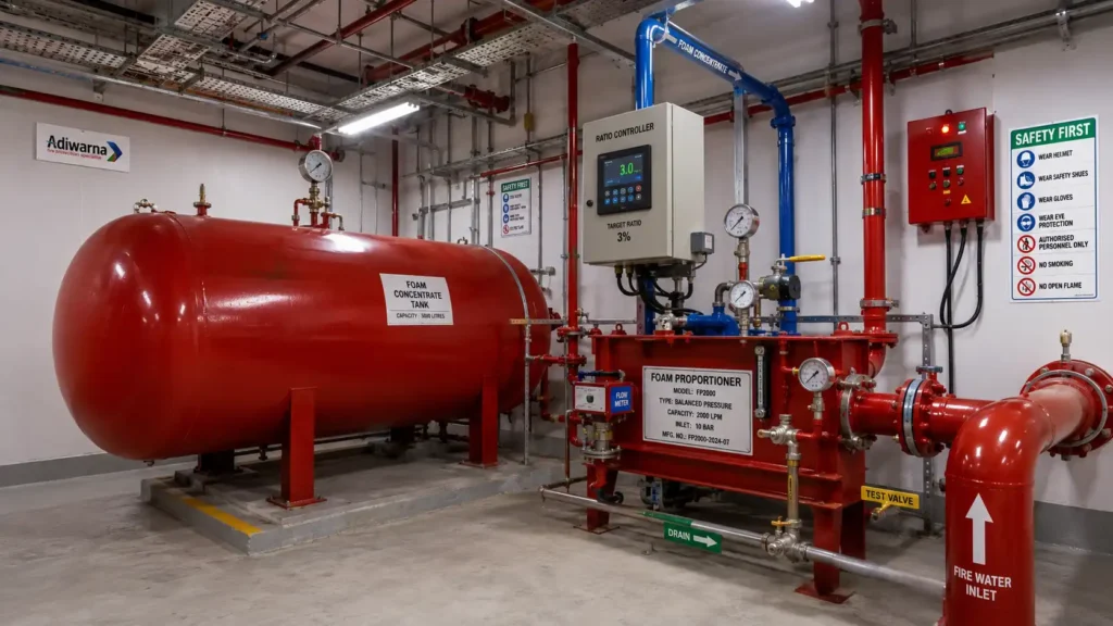
A bladder tank is a pressure vessel fitted with an internal elastomeric bladder that stores foam concentrate and delivers it to a foam proportioner using pressure from the fire water network. It is an essential component of many fixed foam fire fighting systems protecting tank farms, refineries, fuel terminals, loading racks, petrochemical plants, aircraft hangars, and other high-risk industrial facilities.
When the system operates, pressurized water enters the space between the tank shell and the bladder. The water pressure compresses the internal bladder and forces the foam concentrate toward the ratio controller or proportioner. The concentrate is then mixed with water at a specified ratio before the resulting foam solution is distributed to foam monitors, foam chambers, sprinklers, or nozzles.
This arrangement allows the system to produce foam solution without a dedicated foam concentrate pump in many applications. A bladder tank is therefore commonly selected for fixed systems requiring straightforward operation, automatic response, and reliable proportioning.
PT Adiwarna Anugerah Abadi provides bladder tanks for foam fire fighting systems that can be integrated with fire pumps, foam proportioners, deluge valves, foam monitors, foam chambers, fire alarm systems, and control equipment.
What Is a Bladder Tank?
A bladder tank is a pressurized vessel containing two separate internal spaces:
- A water space between the tank shell and the bladder.
- An elastomeric bladder containing the foam concentrate.
The concentrate does not mix directly with the water inside the tank because the bladder separates the two fluids. When fire water enters the vessel, its pressure is applied uniformly to the outside surface of the bladder.
This pressure forces the concentrate through the concentrate outlet and toward the ratio controller. At the controller, the concentrate is introduced into the fire water stream at the required proportioning ratio.
A typical operating sequence is:
- The fire pump supplies water from the fire water tank.
- Fire water flows toward the bladder tank and proportioner.
- Part of the water enters the space surrounding the bladder.
- Water pressure compresses the bladder.
- Foam concentrate is forced out of the tank.
- The concentrate enters the ratio controller.
- Water and concentrate form a foam solution.
- The solution is distributed to the discharge equipment.
- Air is introduced at the discharge device to create finished foam.
- Finished foam is applied to the fire or fuel surface.
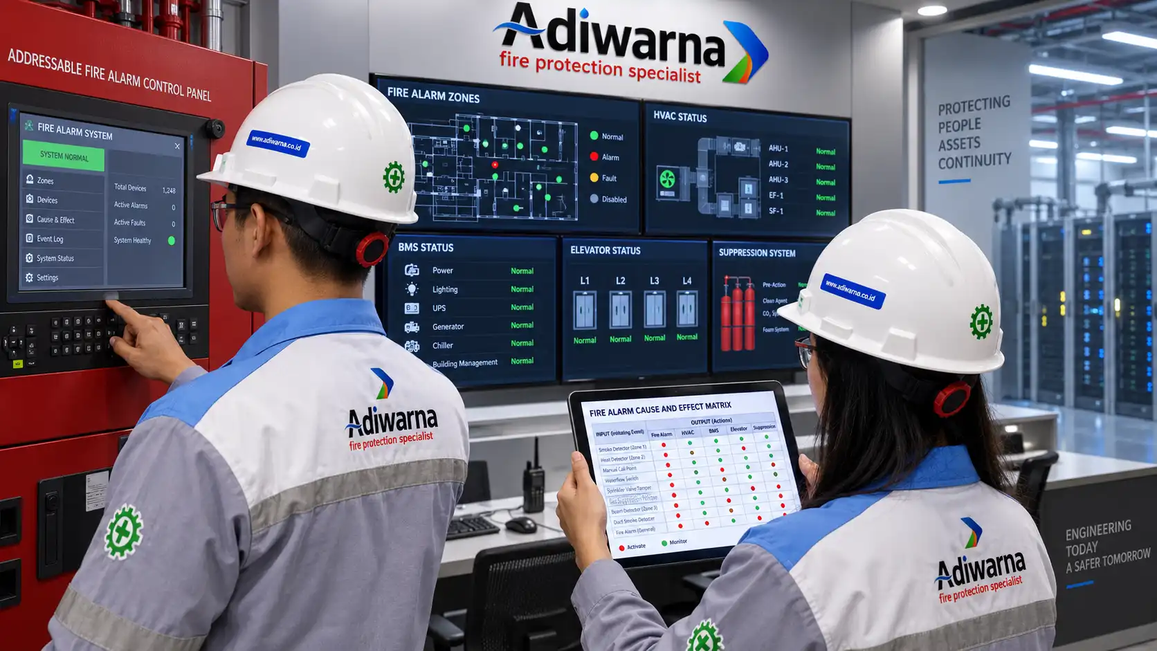
For integrated protection, Adiwarna’s foam fire fighting systems for high-risk areas can combine fire water tanks, electric and diesel fire pumps, bladder tanks, proportioners, monitors, foam chambers, deluge valves, fire alarms, and control panels.
Why Is a Bladder Tank Important?
Foam concentrate must enter the water stream at the correct concentration. Inaccurate proportioning may create a foam blanket that forms too slowly, collapses prematurely, or cannot adequately suppress fuel vapors.
A bladder tank supplies concentrate at a pressure that follows the available fire water pressure. This allows the ratio controller to introduce concentrate into the water stream without requiring a separate concentrate pump in many configurations.
Its main advantages include:
- No dedicated foam pump required in many applications.
- No additional electrical power required to transfer concentrate.
- Relatively straightforward mechanical arrangement.
- Suitable for fixed foam systems.
- Automatic operation after fire water begins flowing.
- Relatively few moving components.
- Easy integration with deluge systems.
- Support for foam monitors and foam chambers.
- Concentrate storage within a closed pressure vessel.
However, the tank must still be selected according to hydraulic demand, concentrate volume, vessel pressure rating, foam type, and the proportioner’s operating flow range.
How a Bladder Tank Works in a Foam System
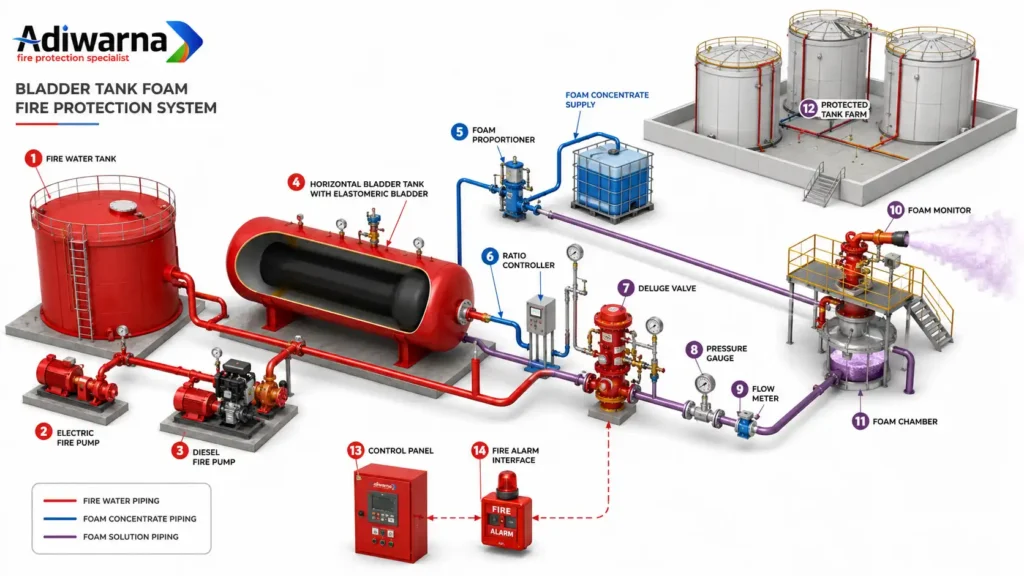
A bladder tank operates through pressure transfer between the fire water and foam concentrate.
While the system is in standby, the bladder contains concentrate and all valves remain in their normal positions. The bladder is not yet being compressed by full operating water pressure.
When a deluge valve, foam control valve, or discharge outlet opens, fire water begins flowing through the network. At the same time, pressurized water enters the space outside the bladder.
The bladder compresses in a controlled manner and pushes concentrate toward the proportioner. Because the transfer pressure is supplied by the same fire water network, concentrate pressure generally follows changes in water pressure.
The ratio controller creates the pressure differential required to introduce concentrate into the water stream. The resulting foam solution is then distributed to the protected area.
Adiwarna’s overview of the bladder tank as a critical foam-system component explains why the equipment requires professional installation, testing, and maintenance.
Bladder Tank and Foam Proportioner
A bladder tank and foam proportioner perform different functions.
The bladder tank:
- Stores foam concentrate.
- Separates concentrate from fire water.
- Transfers water pressure to the concentrate.
- Forces concentrate toward the proportioner.
The foam proportioner:
- Controls how much concentrate enters the water stream.
- Maintains the specified mixing ratio.
- Produces foam solution across an approved flow range.
A bladder tank cannot provide effective protection by itself. It requires a compatible ratio controller or proportioning device selected for the foam concentrate, discharge equipment, and hydraulic conditions.
More information is available in Adiwarna’s article about the foam proportioner for industrial fire fighting systems.
Main Components of a Bladder Tank System
A complete system includes more than the pressure vessel and internal bladder. Typical components include:
- Pressure vessel.
- Elastomeric bladder.
- Foam concentrate filling connection.
- Concentrate drain connection.
- Water inlet.
- Water drain.
- Concentrate outlet.
- Pressure gauges.
- Level or sight indication where provided.
- Isolation valves.
- Check valves.
- Safety or relief device where required.
- Ratio controller.
- Foam concentrate piping.
- Fire water piping.
- Foam solution piping.
- Test connection.
- Drain connection.
- Support saddles or mounting structure.
- Equipment nameplate.
- Inspection opening.
- Foam control valve.
- Deluge valve.
- Fire alarm interface.
Every valve should be clearly identified and returned to its normal position after testing or maintenance.
Vertical and Horizontal Bladder Tanks
Bladder tanks are commonly available in vertical and horizontal configurations.
Vertical Bladder Tank
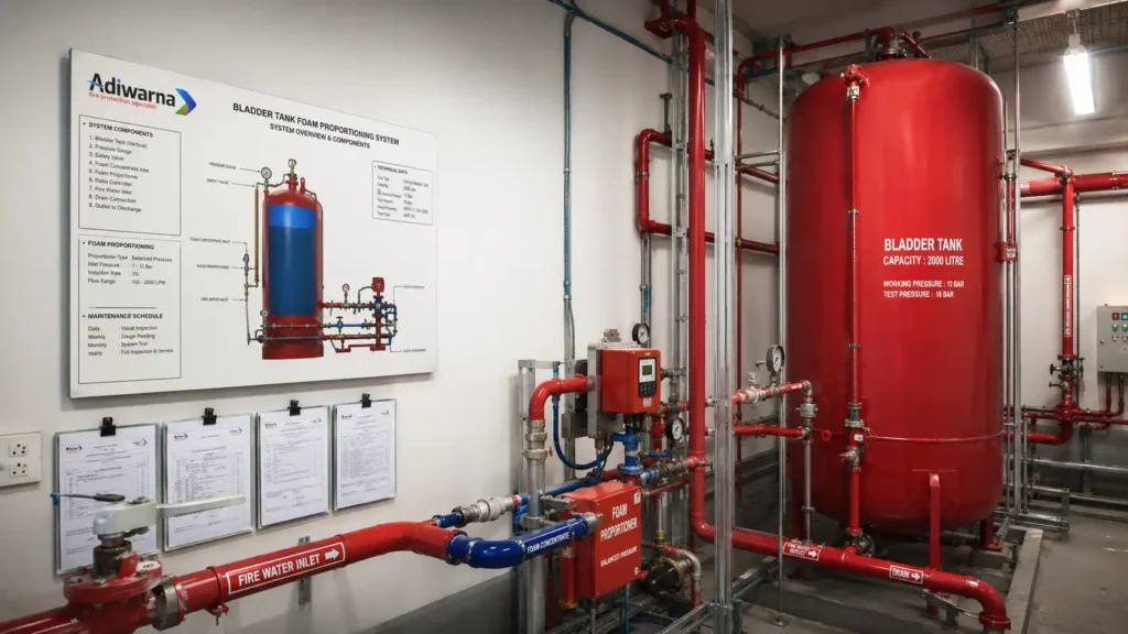
A vertical tank requires less floor area but greater overhead clearance.
This arrangement may be suitable when:
- Floor space is limited.
- Sufficient ceiling height is available.
- Piping can be arranged vertically.
- Filling and maintenance connections remain accessible.
The design must still consider structural support, inspection access, headroom, and bladder replacement requirements.
Horizontal Bladder Tank
A horizontal tank is mounted on support saddles and requires a longer floor footprint.
Possible advantages include:
- Lower overall installation height.
- Easier access to selected connections.
- Suitability for rooms with limited headroom.
- Stable support for larger tank capacities.
Orientation should not be selected only according to available space. Tank capacity, piping arrangement, maintenance clearance, structural loading, and bladder-replacement procedures must also be considered.
Bladder Tank for Tank Farm Protection
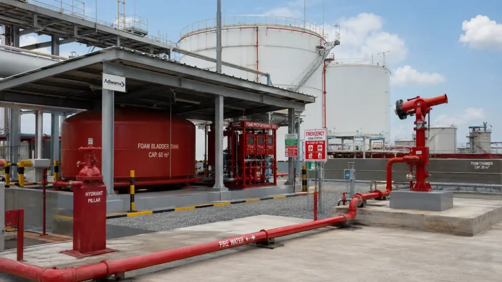
Tank farms are among the most common bladder tank applications because they store large quantities of flammable liquids.
Foam solution can be distributed to:
- Foam chambers.
- Foam pourers.
- Fixed foam monitors.
- Mobile monitor connections.
- Dike or bund protection systems.
- Foam-water sprinklers.
- Deluge nozzles.
A foam chamber applies low-expansion foam relatively gently onto the liquid surface inside a storage tank. This helps minimize plunging and reduces fuel contamination of the foam blanket.
Tank farm design should consider:
- Fuel type.
- Storage-tank diameter.
- Fuel surface area.
- Required application rate.
- Discharge duration.
- Number of foam chambers.
- Number of tanks being protected.
- Simultaneous system demand.
- Bund-area protection.
- Cooling-water demand.
- Foam concentrate percentage.
- Residual concentrate volume.
- Available fire water supply.
- Concentrate-refilling strategy.
Adiwarna also discusses this application through its bladder tank foam fire fighting system information.
Bladder Tank for Oil and Gas Facilities
Oil and gas facilities may use fixed foam systems to protect:
- Loading racks.
- Pump stations.
- Fuel-transfer areas.
- Process areas.
- Tank farms.
- Refineries.
- Marine terminals.
- Jetties.
- Hydrocarbon storage areas.
- Spill-containment zones.
The foam system can be integrated with flame detectors, gas detectors, fire and gas controllers, deluge valves, fire pumps, emergency shutdown systems, and control-room monitoring.
When a detector or manual release activates the protection system, the deluge or foam control valve opens and fire water begins flowing. Water pressure then operates the bladder tank, causing concentrate to flow toward the ratio controller.
Bladder Tank for Aircraft Hangars
Aircraft hangars have large open floor areas and may be exposed to aviation-fuel spill hazards.
Depending on the facility design, foam protection may use:
- Foam-water sprinklers.
- Deluge systems.
- Low-expansion foam.
- High-expansion foam.
- Fixed foam monitors.
- Mobile firefighting equipment.
The bladder tank must store enough concentrate to satisfy the required application rate and discharge duration.
The design should also consider floor drainage, environmental containment, aircraft arrangement, ventilation, system activation logic, and evacuation procedures.
How to Determine Bladder Tank Capacity
Tank capacity should not be selected only according to standard sizes available from the supplier.
The calculation begins with the required foam solution demand:
Required foam concentrate volume = foam solution flow × concentrate percentage × discharge duration
For example, when a system requires 2,000 liters of foam solution per minute, uses 3% concentrate, and must operate for 20 minutes:
2,000 × 0.03 × 20 = 1,200 liters of foam concentrate
This basic result may not represent the final nominal tank capacity. Engineers should also consider:
- Concentrate that cannot be fully discharged.
- Filling tolerances.
- Design safety allowance.
- Simultaneously operating systems.
- Testing allowance.
- Manufacturer requirements.
- Minimum usable tank volume.
- Future facility expansion.
The final bladder tank may therefore be selected at a nominal capacity greater than the basic calculated requirement.
Effect of 1%, 3%, and 6% Foam Ratios
The foam concentrate percentage directly affects the required bladder tank capacity.
For the same amount of foam solution:
- A 1% foam requires the smallest concentrate volume.
- A 3% foam requires three times the volume of a 1% product.
- A 6% foam requires twice the volume of a 3% product.
However, different concentration products are not automatically interchangeable. The ratio controller, metering orifice, bladder tank, concentrate piping, viscosity, minimum flow, and discharge devices must all be evaluated.
Changing from 3% to 1% concentrate may reduce storage requirements, but it does not guarantee that the existing proportioner can remain in service.
Compatibility with Foam Concentrate
The bladder, seals, gaskets, piping, and proportioner must be compatible with the selected concentrate.
Possible concentrate types include:
- AFFF.
- AR-AFFF.
- Fluorine-free foam.
- Protein foam.
- Fluoroprotein foam.
- Class A foam.
- High-expansion concentrate.
Important compatibility factors include:
- Chemical compatibility.
- Concentrate viscosity.
- Storage temperature.
- Elastomer compatibility.
- Seal and gasket compatibility.
- Product approval.
- Proportioning range.
- Water compatibility.
- Discharge-device compatibility.
Adiwarna provides various foam concentrate products for industrial, marine, aviation, petrochemical, and oil and gas applications.
Converting from AFFF to Fluorine-Free Foam
Converting an existing system to fluorine-free foam generally requires more than draining the AFFF and filling the tank with a new product.
The assessment may need to cover:
- Existing bladder condition.
- Material compatibility.
- Residual contamination.
- Tank cleaning.
- Concentrate piping cleaning.
- Seal and gasket compatibility.
- New concentrate viscosity.
- Ratio-controller operating range.
- Minimum operating flow.
- Required application rate.
- Discharge devices.
- Product approvals.
- Proportioning tests.
- Disposal of the previous concentrate.
Some fluorine-free products have different viscosity and discharge characteristics from AFFF. Existing bladder tank systems may therefore require hardware modification or replacement.
Hydraulic Calculations
Hydraulic calculations confirm that the foam solution reaches every discharge device at the required flow and pressure.
The calculation should include:
- Fire water flow.
- Foam solution flow.
- Pipe diameters.
- Fitting losses.
- Elevation differences.
- Ratio-controller pressure loss.
- Deluge-valve pressure loss.
- Foam chamber inlet pressure.
- Foam monitor pressure.
- Nozzle pressure.
- Minimum and maximum system flow.
- Fire pump operating point.
The bladder tank depends on available fire water pressure. That pressure must therefore be sufficient to operate the tank, proportioner, control valve, piping, and discharge equipment.
Excessive pressure loss may prevent a monitor, nozzle, or foam chamber from producing the required discharge pattern.
Standards for Bladder Tanks and Foam Systems
Design and installation should follow applicable standards, local regulations, manufacturer instructions, and project specifications.
Common references include:
- NFPA 11 for low-, medium-, and high-expansion foam.
- NFPA 20 for stationary fire pumps.
- NFPA 25 for inspection, testing, and maintenance of water-based systems.
- NFPA 72 for fire alarm and signaling systems.
- Applicable UL or FM requirements.
- Manufacturer datasheets.
- Pressure-vessel requirements.
- Environmental regulations.
- Company HSE standards.
- Applicable Indonesian standards and local regulations.
NFPA 11 provides the main technical framework for foam systems, while NFPA 25 supports ongoing inspection, testing, and maintenance.
Bladder Tank Installation
A typical installation process includes:
- Reviewing approved drawings and equipment datasheets.
- Verifying the tank capacity and pressure rating.
- Preparing the foundation or support structure.
- Installing the tank in the approved orientation.
- Connecting the fire water inlet.
- Connecting the concentrate outlet.
- Installing the ratio controller.
- Installing pressure gauges and test connections.
- Verifying the correct direction of flow.
- Flushing the water piping.
- Performing leakage or pressure testing.
- Filling the tank with foam concentrate.
- Venting trapped air according to the manufacturer’s procedure.
- Returning all valves to their normal positions.
- Conducting a proportioning test.
- Testing alarms and control interfaces.
- Preparing complete commissioning records.
The internal bladder must not be damaged during filling. Manufacturer procedures should be followed to prevent folding, twisting, overfilling, or trapped air.
Testing and Commissioning

Testing must demonstrate that the tank supplies concentrate correctly and produces foam solution at the required ratio.
Commissioning activities may include:
- Visual inspection.
- Nameplate verification.
- Valve-position checks.
- Pressure testing.
- Leakage inspection.
- Bladder integrity inspection.
- Concentrate identification.
- Fill-level verification.
- Water-side testing.
- Ratio-controller testing.
- Proportioning tests.
- Flow measurement.
- Pressure measurement.
- Deluge-valve testing.
- Foam-monitor testing.
- Foam-chamber inspection.
- Fire alarm interface testing.
- Low-level alarm testing where installed.
- System-restoration verification.
A proportioning test may use refractive-index measurement, conductivity testing, flow measurement, or another approved method.
Observing foam discharge from a monitor does not prove that the concentration is correct. A foam solution sample must be tested against an appropriate calibration curve.
Bladder Tank Maintenance
A bladder tank requires routine inspection even though it may not use a dedicated concentrate pump.
Maintenance checks may include:
- Tank shell condition.
- Corrosion.
- Leakage.
- Pressure gauges.
- Valve positions.
- Concentrate level.
- Concentrate quality.
- Bladder integrity.
- Piping connections.
- Ratio controller.
- Strainers.
- Check valves.
- Drain connections.
- Supports and anchors.
- Labels and nameplates.
- Previous inspection records.
The bladder can be damaged by age, chemical incompatibility, overpressure, improper filling, or incorrect maintenance procedures.
After testing, all valves must be returned to their normal positions and any concentrate used during the test must be replenished.
Signs of Bladder Tank Problems
Conditions requiring immediate investigation include:
- Foam concentrate entering the water side.
- Water found inside the concentrate.
- Incorrect foam concentration.
- No concentrate flow.
- Unstable operating pressure.
- Tank leakage.
- Suspected bladder rupture.
- Abnormal pressure-gauge indication.
- Valves that are difficult to operate.
- Blocked strainers.
- Proportioner failure at minimum flow.
- Unexplained concentrate loss.
- Corrosion on the vessel shell or connections.
When the bladder ruptures, fire water and concentrate may mix inside the pressure vessel. The system must then be isolated, drained, internally inspected, and the bladder may need replacement.
Common Bladder Tank Project Mistakes
Common mistakes include:
- Selecting an undersized tank.
- Using the wrong foam concentration.
- Installing a bladder incompatible with the concentrate.
- Oversizing the ratio controller.
- Operating below the minimum flow.
- Installing the proportioner in the wrong flow direction.
- Using an incorrect valve arrangement.
- Mixing different concentrate products.
- Providing inadequate maintenance clearance.
- Installing an unsuitable foundation.
- Failing to provide drainage.
- Filling the tank without following the manufacturer’s procedure.
- Leaving trapped air inside the bladder.
- Skipping the proportioning test.
- Failing to return valves to standby positions.
- Converting to fluorine-free foam without technical evaluation.
- Providing incomplete commissioning records.
A foam system can appear mechanically complete while still failing to produce the correct foam solution if one component is incorrectly selected or configured.
Benefits of a Properly Designed Bladder Tank System
A correctly designed and installed system provides several advantages:
- Concentrate storage inside a closed pressure vessel.
- No dedicated foam concentrate pump in many applications.
- Automatic pressure transfer from the fire water network.
- Relatively straightforward mechanical arrangement.
- Easy integration with deluge systems.
- Compatibility with foam monitors and foam chambers.
- Reduced reliance on an additional power source.
- Suitability for fixed industrial foam protection.
- Straightforward monitoring and testing.
- Effective application in tank farms and oil and gas facilities.
These benefits depend on correct tank capacity, compatibility, hydraulic design, proportioning accuracy, testing, and maintenance.
Why Choose PT Adiwarna Anugerah Abadi?
PT Adiwarna Anugerah Abadi can help companies select a bladder tank according to the protected fuel, foam concentrate, required application rate, operating duration, hydraulic demand, and project standards.
The service scope may include:
- Site surveys.
- Fire risk assessments.
- Foam-demand calculations.
- Bladder tank sizing.
- Foam concentrate selection.
- Ratio-controller selection.
- Hydraulic calculations.
- Engineering design.
- Procurement.
- Installation.
- Filling and system preparation.
- Testing and commissioning.
- Proportioning tests.
- Preventive maintenance.
- Bladder replacement.
- System conversion and upgrades.
Through its industrial foam fire fighting system services, Adiwarna can integrate bladder tanks with fire pumps, foam proportioners, deluge valves, foam monitors, foam chambers, fire alarm systems, and control equipment.
For complete project execution, Adiwarna EPC Fire Protection can support engineering, procurement, construction, testing, commissioning, and maintenance.
Companies requiring consultation can contact PT Adiwarna Anugerah Abadi through the Adiwarna website.
Conclusion
A bladder tank is a pressure vessel containing an internal elastomeric bladder that stores foam concentrate and supplies it to a proportioner using fire water pressure.
This arrangement allows concentrate to enter the water stream without a dedicated foam pump in many fixed systems. Bladder tanks are therefore widely used for tank farms, refineries, loading racks, fuel terminals, aircraft hangars, petrochemical facilities, and oil and gas operations.
However, system performance depends on more than tank capacity. The foam concentrate, bladder material, ratio controller, fire pump, hydraulic calculations, valve arrangement, discharge devices, testing, and maintenance must be engineered as one integrated system.
With correct selection and commissioning, a bladder tank can provide stable foam concentrate delivery and support reliable protection against flammable-liquid fires.
PT Adiwarna Anugerah Abadi is ready to support bladder tank sizing, procurement, installation, testing, proportioning verification, maintenance, and system upgrades for industrial facilities.