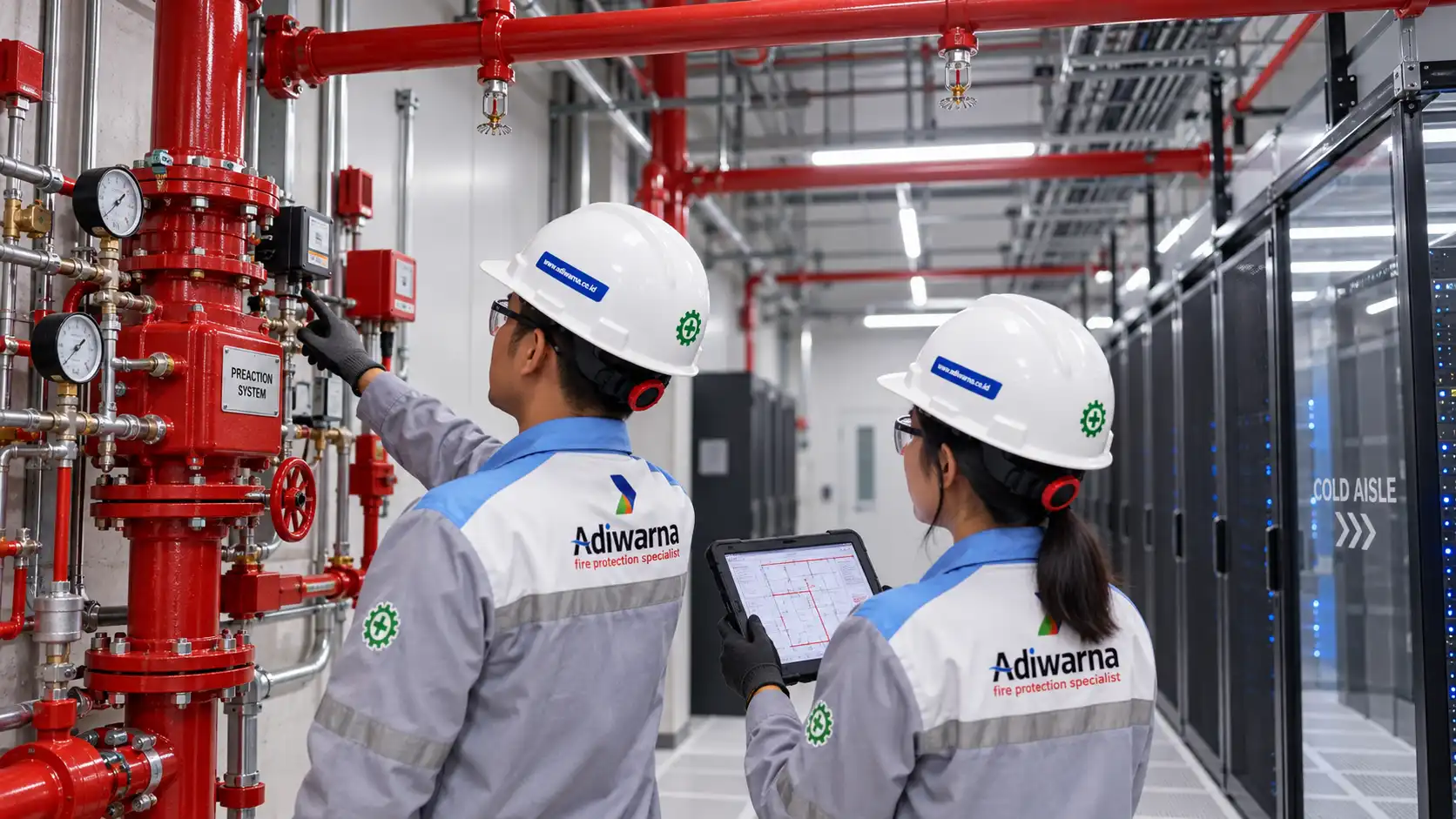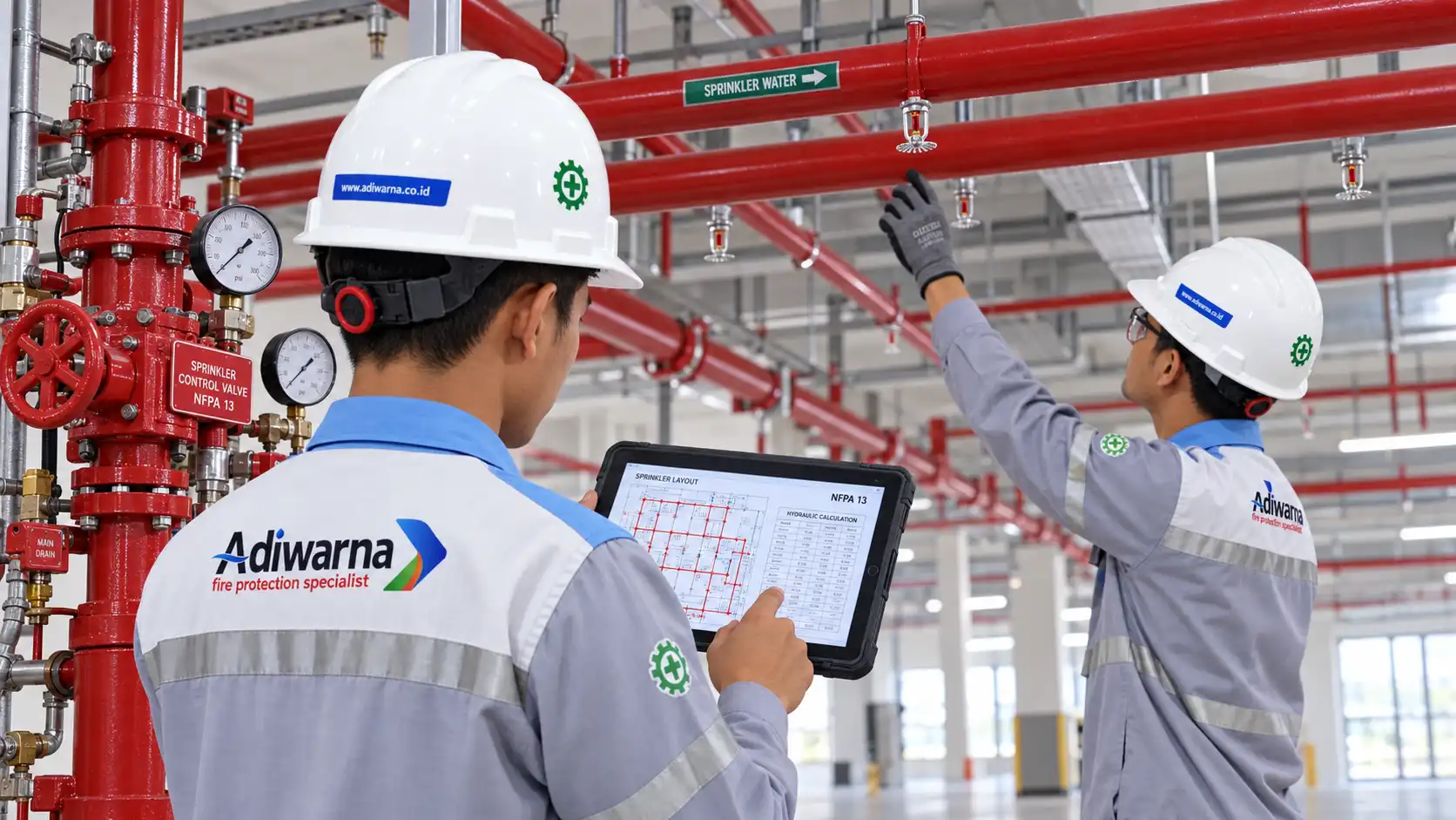

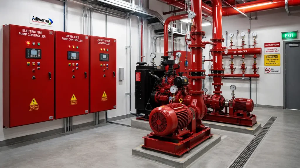
A fire pump controller is a dedicated control panel that manages the starting, operation, monitoring, and alarm functions of a fire pump. It receives signals from a pressure switch or another approved initiating device and then starts an electric fire pump, diesel fire pump, or jockey pump according to the system configuration.
A controller is not simply an ordinary motor starter panel. It is a critical safety component that ensures a pump operates when pressure decreases in a hydrant, sprinkler, deluge, water spray, or foam-water system.
In a typical installation, the electric main fire pump, diesel fire pump, and jockey pump each have a dedicated controller. Every panel uses different power sources, control circuits, alarm functions, and operating methods.
For commercial buildings and industrial facilities, PT Adiwarna Anugerah Abadi provides various fire pump systems, including end-suction pumps, horizontal split-case pumps, vertical turbine pumps, multistage pumps, and jockey pumps that can be supplied with controllers according to project requirements.
What Is a Fire Pump Controller?
A fire pump controller is a device that controls pump starting, monitors the power source, displays operating conditions, and generates alarms when faults occur.
When a pressure switch detects that network pressure has reached the pump-start setpoint, it transmits a signal to the controller. The controller then starts the pump so the system can provide the water flow and pressure required for firefighting.
The main functions of a controller include:
- Starting the fire pump automatically.
- Providing manual-start controls.
- Monitoring the pump power source.
- Displaying pump-running status.
- Generating alarms when faults occur.
- Monitoring the pressure switch and sensing line.
- Transmitting status signals to the fire alarm panel or control room.
- Recording events when the controller includes an event logger.
- Supporting pump testing and maintenance.
- Maintaining the system in a ready condition.
Requirements for stationary fire pump installations, including controllers and supporting equipment, are addressed in NFPA 20.
Why Is a Fire Pump Controller Important?
A fire pump must operate during an emergency, including when no personnel are present in the pump room. Therefore, automatic starting is one of the controller’s most important functions.
When a controller fails to issue a start command, a mechanically functional pump may still be unable to supply water. As a result, hydrants, sprinklers, water spray systems, deluge systems, or foam-water systems may lose the pressure and flow required for fire control.
The controller also helps personnel identify important conditions such as:
- Pump running.
- Power failure.
- Phase failure.
- Phase reversal.
- Controller trouble.
- Diesel engine trouble.
- Starting battery failure.
- Battery charger failure.
- Low fuel.
- Failure to start.
In a fire fighting pump system, the controller works together with the pump, pressure switch, fire water tank, distribution piping, hydrants, and sprinkler system to maintain firefighting water availability.
How a Fire Pump Controller Works
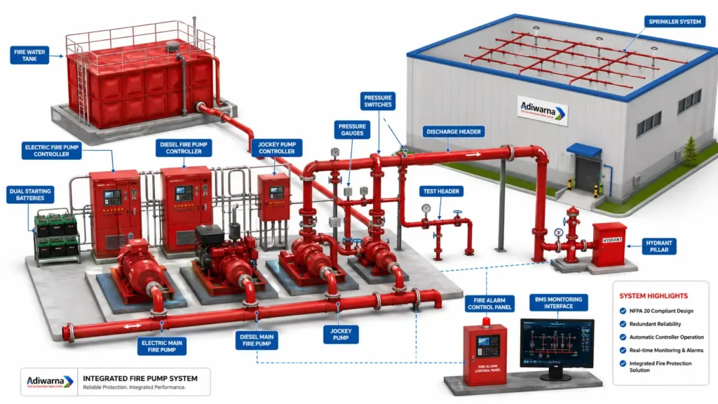
Under normal conditions, the fire water network remains at standby pressure. The jockey pump maintains this pressure and compensates for minor pressure losses.
When a small leak or normal pressure fluctuation occurs, the jockey pump controller starts the jockey pump first. After pressure returns to its normal value, the controller stops the pump according to the configured setpoint.
When a hydrant or sprinkler begins discharging water, system pressure drops further. The electric fire pump controller receives a signal from the pressure switch and starts the main fire pump.
If the electric pump is unavailable or the electrical supply fails, the diesel fire pump may operate according to its start setpoint and the system redundancy philosophy.
A typical operating sequence is:
- The fire water network remains at standby pressure.
- The jockey pump maintains normal system pressure.
- A hydrant, sprinkler, or another outlet begins discharging water.
- Network pressure decreases.
- The pressure switch detects the pressure reduction.
- The jockey pump starts for a minor pressure decrease.
- The electric main fire pump starts when pressure continues to fall.
- The diesel fire pump starts according to its setpoint and system philosophy.
- Pump status is transmitted to the fire alarm panel or control room.
- The system is restored to standby after the emergency has ended.
Controller setpoints must not be selected arbitrarily. They should be established from normal network pressure, hydraulic calculations, pump curves, jockey pump capacity, and the facility’s operating philosophy.
Types of Fire Pump Controllers
Electric Fire Pump Controller
An electric fire pump controller operates a main fire pump driven by an electric motor.
The panel receives a dedicated electrical supply and starts the motor after receiving an automatic or manual start signal. It must be selected according to voltage, phase, motor power, full-load current, starting method, and available electrical capacity.
Typical functions include:
- Automatic start.
- Manual start.
- Emergency manual operation.
- Pump-running indication.
- Power-available indication.
- Phase-failure monitoring.
- Phase-reversal indication.
- Controller-trouble alarm.
- Remote alarm contacts.
- Pressure-switch input.
- Event history on selected models.
The controller receives signals from a pressure-operated switch, sprinkler alarm valve, or remote fire alarm equipment. It then starts the pump motor and monitors its operation. These dedicated safety functions distinguish it from an ordinary utility pump starter. Additional information is available in UL Solutions’ explanation of fire pump controller applications.
Diesel Fire Pump Controller
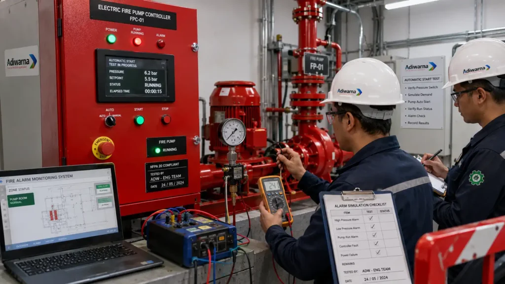
A diesel fire pump controller manages the diesel engine, starting system, battery chargers, and engine alarm conditions.
The panel normally uses two starting batteries. The controller can alternate start attempts between the batteries to improve the likelihood of successful engine starting after receiving an automatic start signal.
Available functions may include:
- Automatic engine start.
- Manual engine start.
- Emergency manual start.
- Dual-battery starting sequence.
- Battery-voltage monitoring.
- Battery-charger monitoring.
- Engine-running indication.
- Failure-to-start alarm.
- Low oil pressure alarm.
- High engine temperature alarm.
- Overspeed alarm.
- Low-fuel indication.
- Remote monitoring outputs.
A diesel fire pump provides a pumping source that does not depend directly on the main electrical supply. It is commonly used in high-rise buildings, factories, warehouses, power plants, and oil and gas facilities.
Jockey Pump Controller
A jockey pump controller operates the smaller pressure-maintenance pump used to maintain standby network pressure.
Unlike a main fire pump, a jockey pump typically uses both automatic start and automatic stop. It starts when pressure reaches the configured start setpoint and stops after pressure reaches the stop setpoint.
Its main functions include:
- Maintaining network pressure.
- Reducing unnecessary main fire pump starts.
- Controlling automatic start and stop.
- Providing motor protection.
- Displaying pump-running status.
- Indicating pump or controller faults.
A jockey pump should not be oversized because it could satisfy a flow demand that should otherwise start the main fire pump. Further information about pressure-maintenance pumps is available on Adiwarna’s jockey pump page.
Differences Between Electric, Diesel, and Jockey Pump Controllers
| Aspect | Electric Controller | Diesel Controller | Jockey Controller |
|---|---|---|---|
| Driver | Electric motor | Diesel engine | Small electric motor |
| Primary function | Starts the main electric fire pump | Starts the diesel fire pump | Maintains network pressure |
| Automatic start | Yes | Yes | Yes |
| Automatic stop | Based on standards and system philosophy | Based on the approved operating procedure | Generally available |
| Power source | Electrical supply | Starting batteries and diesel fuel | Electrical supply |
| Primary monitoring | Power, phases, motor, pump running | Batteries, chargers, engine, and fuel | Pressure, motor, and overload |
| Complexity | High | Most complex | Relatively simple |
An ordinary utility pump starter should not be used in place of a dedicated fire pump controller without verifying its listing, safety functions, and compliance with project requirements.
Automatic Start and Pressure Switches
Automatic starting is normally initiated by a pressure switch connected to a pressure-sensing line.
When pressure reaches a specified value, the pressure-switch contacts change state and transmit a signal to the controller. The controller then starts the pump without waiting for operator intervention.
Depending on the system design, start signals may also originate from:
- Deluge valve operation.
- Remote start stations.
- Fire alarm interfaces.
- Specific flow conditions.
- Manual emergency stations.
- Test circuits.
The sensing line must remain open, clear, and free from leakage. A closed valve or blocked line can prevent the controller from receiving accurate pressure information.
Coordinating Pump Setpoints
Setpoints for the jockey, electric, and diesel pump controllers should be arranged in sequence.
Conceptually:
- The jockey pump starts after the first minor pressure decrease.
- The electric fire pump starts at a lower pressure.
- The diesel fire pump starts at the next setpoint according to the redundancy strategy.
Actual settings should be determined from:
- Normal network pressure.
- Pump churn pressure.
- Hydraulic demand.
- Maximum pipe pressure.
- Elevation differences.
- Normal pressure fluctuations.
- Jockey pump capacity.
- Main pump curves.
- Project operating philosophy.
Poor setpoint coordination can cause all pumps to start together or delay operation of the main fire pump.
Controller Alarms and Indicators
The controller should provide information that operators and technicians can understand quickly.
Common indicators include:
- Power available.
- Pump running.
- Automatic mode.
- Manual mode.
- Controller trouble.
- Phase failure.
- Phase reversal.
- Low battery.
- Charger failure.
- Engine running.
- Failure to start.
- Low fuel.
- High engine temperature.
- Low oil pressure.
- Overspeed.
Not every controller provides the same indications. Required alarm points should therefore be defined in the technical specification and facility monitoring requirements.
Integration with the Fire Alarm Control Panel
The fire pump controller and fire alarm control panel have different responsibilities.
The controller starts and monitors the pump, while the fire alarm panel receives status signals for display in the fire command center or control room.
Signals that may be transmitted include:
- Electric fire pump running.
- Diesel fire pump running.
- Jockey pump running.
- Controller trouble.
- Power failure.
- Phase reversal.
- Engine trouble.
- Charger failure.
- Low fuel.
- Common alarm.
Adiwarna’s article about the master control fire alarm system explains how a main fire alarm panel can receive conditions such as pump running, pump failure, controller trouble, and power failure from the fire pump installation.
The fire alarm panel acts as a monitoring interface and does not replace the dedicated pump controller.
Integration with BMS and the Control Room
In large facilities, controller status may also be transmitted to a building management system, SCADA platform, or control-room workstation.
Displayed information may include:
- Pump-running status.
- Standby condition.
- Power condition.
- Controller trouble.
- Engine trouble.
- Fuel alarm.
- Battery alarm.
- Network pressure.
- Event history.
However, the basic fire pump starting function should not depend entirely on the BMS communication network. Automatic starting must remain locally controlled by the dedicated fire pump controller.
Fire Pump Controllers for Hydrant and Sprinkler Systems
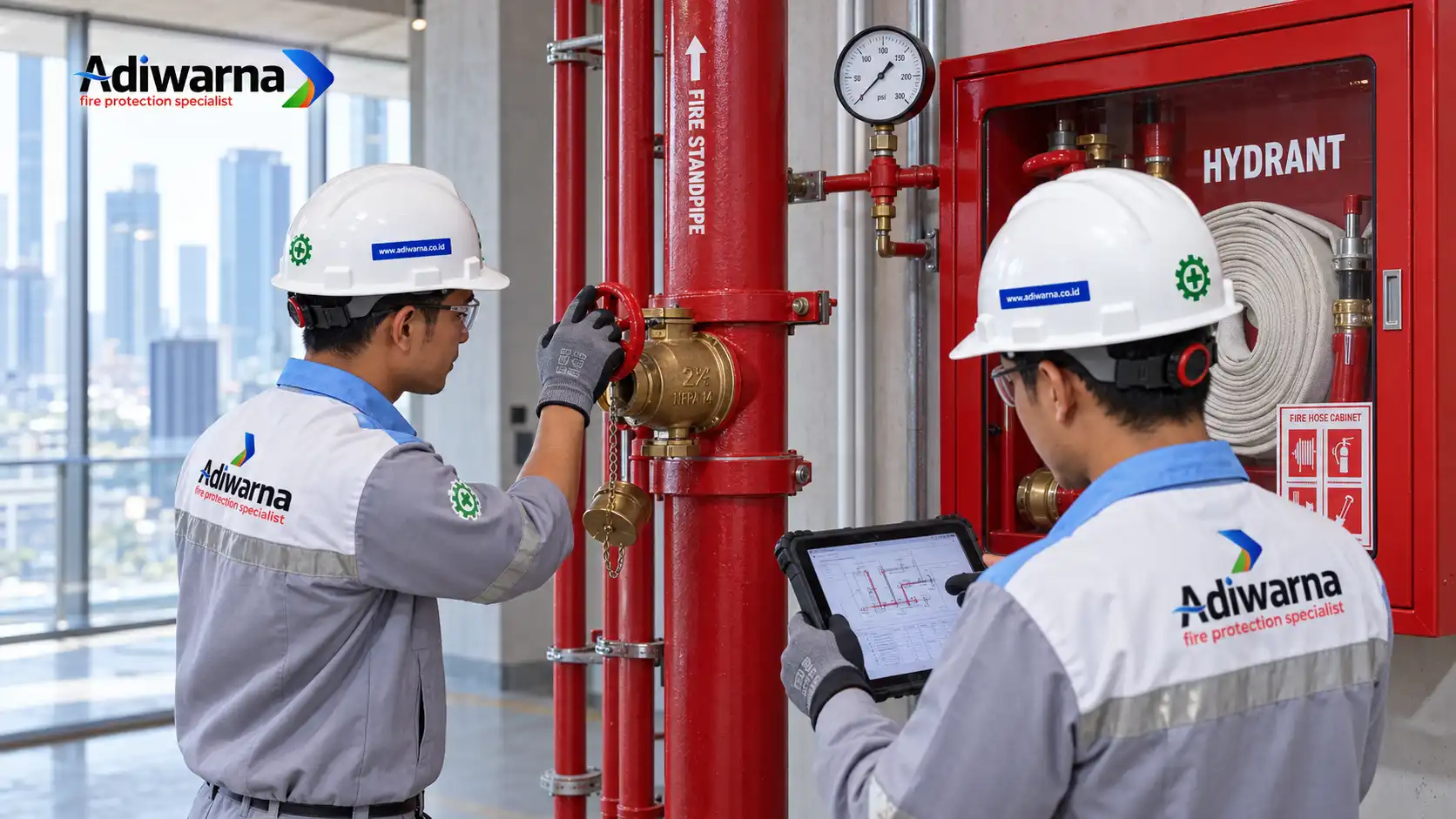
In a hydrant system, the controller starts the pump when use of a hydrant pillar, hydrant box, landing valve, or hose reel causes network pressure to decrease.
A complete system may include:
- Fire water tank.
- Electric main fire pump.
- Diesel fire pump.
- Jockey pump.
- Individual fire pump controllers.
- Suction and discharge headers.
- Pressure switches.
- Hydrant pillars.
- Hydrant boxes.
- Sprinkler piping.
- Fire alarm monitoring.
One fire pump set may also serve sprinklers, deluge systems, or foam-water systems when the pump capacity and fire water storage have been calculated according to the applicable simultaneous demand.
For a deluge system, a high flow demand may occur immediately after the deluge valve opens. Therefore, the fire pump, controller, and water supply must be selected according to hydraulic demand rather than only the motor rating.
Fire Pump Controller Standards
References commonly considered in fire pump controller design include:
- NFPA 20 for stationary fire pump installations.
- NFPA 25 for inspection, testing, and maintenance.
- NFPA 72 for fire alarm and signaling systems.
- NFPA 24 for private fire service mains.
- UL 218 for fire pump controllers.
- FM Approval requirements when specified.
- Applicable Indonesian standards and fire regulations.
- Manufacturer instructions.
- Project technical specifications.
UL Solutions explains that UL 218 is used to evaluate fire pump controller safety, while NFPA 20 addresses the application of controllers in stationary fire pump installations.
Difference Between NFPA Compliant, UL Listed, and FM Approved
These terms do not have the same meaning.
NFPA compliant refers to applying relevant NFPA requirements to the design and installation.
UL Listed means that a product has been evaluated under the listing standard applicable to its equipment category.
FM Approved means that the product has been evaluated according to FM approval criteria for a particular application.
A controller described as NFPA compliant is not automatically UL Listed or FM Approved. Conversely, a listed controller must still be installed, configured, tested, and maintained correctly.
Fire Pump Controller Selection Factors
Before choosing a controller, engineers should verify:
- Pump type and driver.
- Motor power or engine type.
- Rated voltage.
- Frequency.
- Number of phases.
- Full-load current.
- Starting method.
- Available electrical supply.
- Short-circuit rating.
- Enclosure rating.
- Ambient temperature.
- Humidity.
- Required alarm points.
- Remote monitoring requirements.
- Required product listing.
- Spare-parts availability.
- Maintenance support.
The controller must be correctly rated for the motor or engine it operates. An incorrectly sized panel may fail during starting or may not provide the required monitoring functions.
Testing and Commissioning
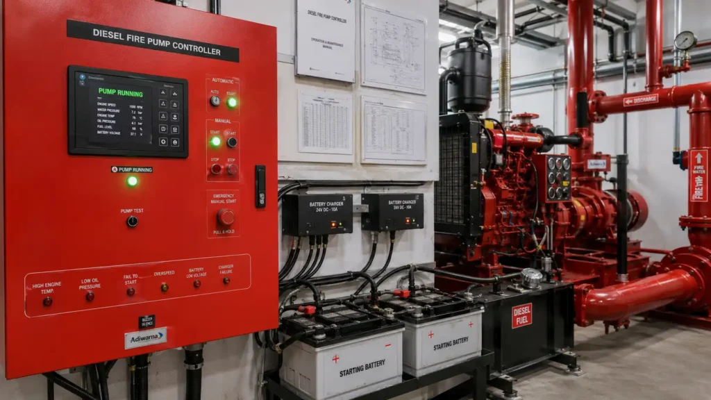
Testing must demonstrate that the controller can start the pump and generate the required alarm signals.
Initial checks may include:
- Nameplate and rating verification.
- Enclosure condition.
- Wiring and terminal inspection.
- Earthing.
- Power-supply verification.
- Phase rotation.
- Pressure-switch connections.
- Sensing-line condition.
- Battery connections.
- Charger operation.
- Fuel-level interfaces.
- Remote alarm wiring.
- Selector-switch position.
Functional tests may include:
- Automatic start testing.
- Manual start testing.
- Emergency manual operation.
- Pressure-switch testing.
- Pump-running indication.
- Power-failure simulation.
- Phase-reversal testing.
- Controller-trouble simulation.
- Battery-failure testing.
- Charger-failure testing.
- Diesel starting-sequence testing.
- Failure-to-start testing.
- Remote alarm testing.
- Fire alarm interface testing.
- Event-history verification.
- Restoration to automatic mode.
Controller testing should be performed together with fire pump acceptance testing. A controller that successfully starts the pump does not prove that the pump provides the required flow and pressure.
Flow Testing and the Controller’s Role
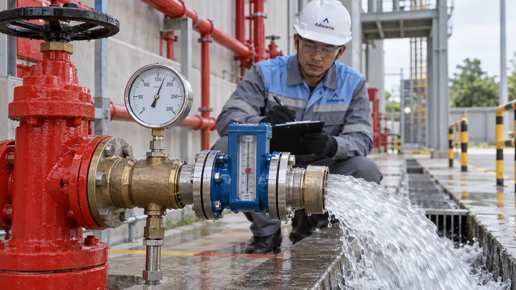
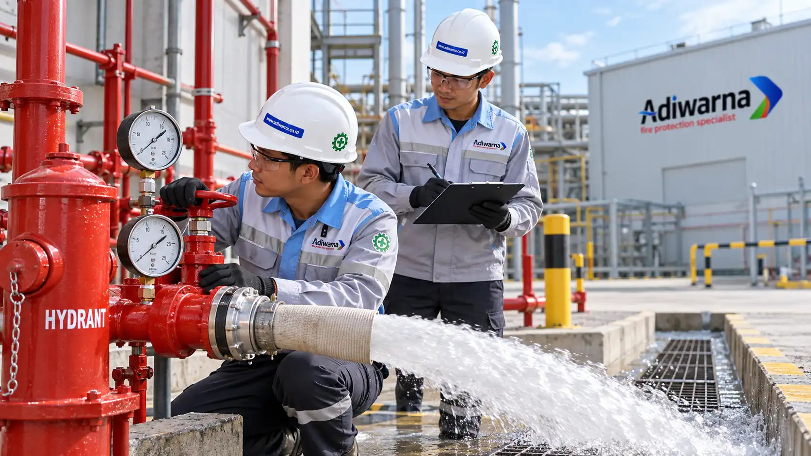
During a flow test, the controller starts and operates the fire pump while technicians measure:
- Suction pressure.
- Discharge pressure.
- Net pump pressure.
- Flow rate.
- Motor voltage.
- Motor current.
- Diesel engine speed.
- Alarm status.
- Controller response.
The test data is then compared with the approved pump curve.
A “pump running” indication only confirms that the pump received an operating command. Hydraulic performance must still be confirmed through flow testing.
Inspection and Maintenance
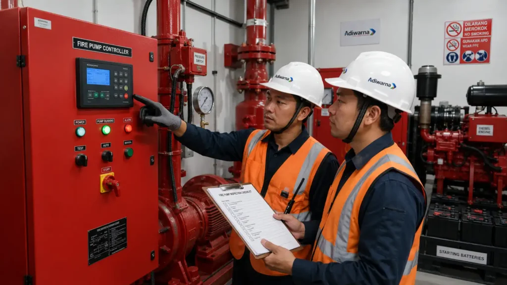
A fire pump controller requires periodic inspection to ensure the system remains ready for emergency operation.
Inspections may cover:
- Enclosure condition.
- Panel cleanliness.
- Indicator lights.
- Display condition.
- Selector-switch position.
- Power availability.
- Terminal connections.
- Corrosion and moisture.
- Pressure switch.
- Sensing line.
- Battery voltage.
- Battery chargers.
- Alarm contacts.
- Communication interfaces.
- Event logs.
- Wiring diagrams and labels.
NFPA 25 is commonly referenced for the inspection, testing, and maintenance of water-based fire protection systems, including fire pumps and related failure conditions.
After maintenance, technicians should verify that:
- The controller has been returned to automatic mode.
- All bypasses have been removed.
- Alarms have been reset.
- The sensing-line valve is open.
- Battery chargers are operating.
- The power supply is normal.
- Remote monitoring is active.
- No unresolved trouble condition remains.
Common Installation Mistakes
Common mistakes include:
- Using an ordinary starter panel.
- Selecting a controller with an incorrect motor rating.
- Failing to verify starting current.
- Providing an unreliable power supply.
- Installing undersized cables.
- Providing inadequate earthing.
- Failing to calibrate the pressure switch.
- Leaving the sensing line closed or obstructed.
- Failing to coordinate pump setpoints.
- Oversizing the jockey pump.
- Failing to connect alarm contacts.
- Leaving the controller in manual or off mode.
- Allowing the battery charger to remain faulty.
- Using an unsuitable enclosure rating.
- Skipping integrated system testing.
- Failing to retain commissioning records.
Recurring faults should not simply be reset. The cause must be investigated through the power supply, sensing line, wiring, controller, pressure switch, and pump condition.
Why Choose PT Adiwarna Anugerah Abadi?
PT Adiwarna Anugerah Abadi can assist companies in selecting fire pumps and controllers according to hydraulic demand, driver type, power source, redundancy requirements, and project standards.
The service scope may include:
- Site surveys.
- Hydraulic calculations.
- Fire pump selection.
- Controller selection.
- Electrical load reviews.
- Engineering design.
- Procurement.
- Installation.
- Cable termination.
- Fire alarm integration.
- Testing and commissioning.
- Flow testing.
- Troubleshooting.
- Preventive maintenance.
- System upgrades.
Through Adiwarna’s Fire Fighting Pump services, companies can receive support for design and engineering, equipment supply, installation, testing, commissioning, service, and maintenance.
For projects requiring an integrated scope, Adiwarna EPC Fire Protection can coordinate fire pumps, controllers, hydrants, sprinklers, alarms, deluge systems, and foam systems.
Consultation, procurement, testing, and maintenance requirements can be submitted through the PT Adiwarna Anugerah Abadi website.
Conclusion
A fire pump controller is an essential device that manages automatic starting, manual operation, alarms, and monitoring for electric fire pumps, diesel fire pumps, and jockey pumps.
During an emergency, the controller ensures that the pump starts after network pressure decreases or another approved activation signal is received. It also helps operators identify pump-running conditions, power failures, controller trouble, battery failures, charger failures, and other system faults.
However, system reliability is not determined by the controller alone. The pump, motor or engine, pressure switch, sensing line, power source, batteries, alarm interfaces, hydraulic calculations, testing, and maintenance must be engineered as one coordinated system.
With correct selection, installation, and commissioning, the controller helps maintain the firefighting water supply required by hydrants, sprinklers, deluge systems, water spray systems, and foam-water systems.
PT Adiwarna Anugerah Abadi is ready to support fire pump controller selection, installation, testing, commissioning, troubleshooting, and maintenance for commercial buildings and industrial facilities.