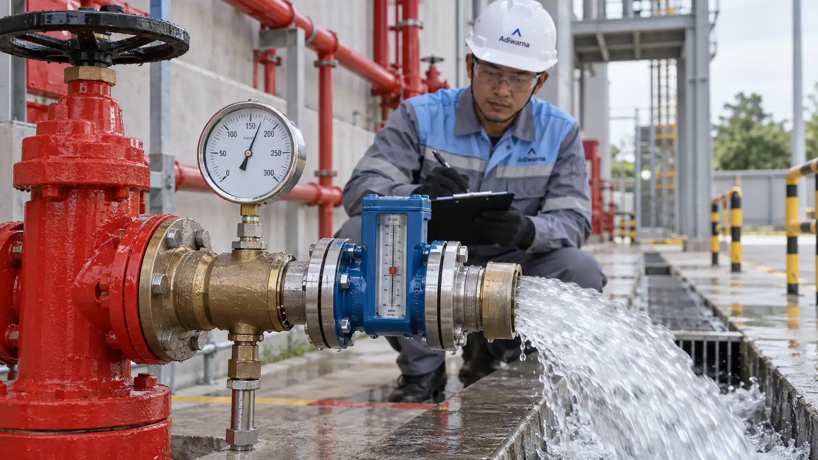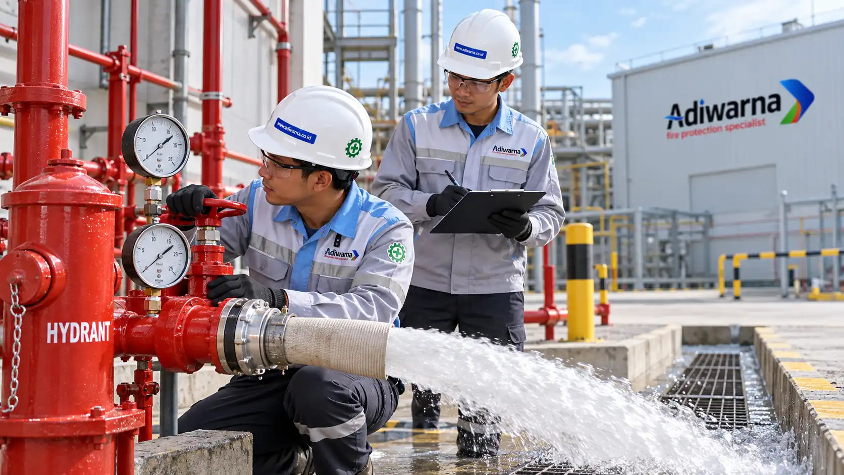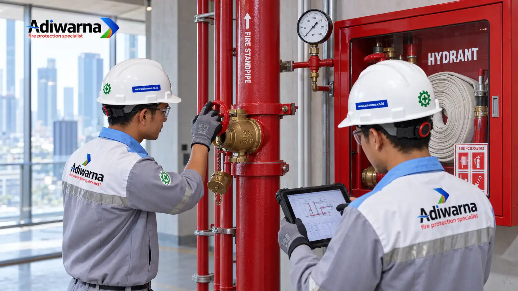

A hydrant flow test system should not only be checked for physical installation. The piping network, hydrant pillars, landing valves, fire pump, and supporting components must also provide the required pressure and flow when needed.
This is why a hydrant flow test is important. The test measures the actual ability of a hydrant system to deliver water through a selected test point.
The test results are then compared with the hydraulic design, project specifications, owner requirements, and authority having jurisdiction or AHJ requirements.
In general, a hydrant flow test may form part of acceptance testing, testing and commissioning, periodic inspection, or performance evaluation of an operating hydrant system.
Quick Answer: What Is a Hydrant Flow Test?
A hydrant flow test measures water flow rate, static pressure, and residual pressure in a hydrant system or fire water network.
The test helps determine:
- Water pressure when there is no flow.
- Water pressure while water is flowing.
- Flow rate available from the system.
- Actual condition of the piping network and valves.
- Fire pump response to pressure changes.
- System performance compared with the hydraulic calculation.
The test method and test location must match the system type, hydraulic design, site condition, project requirements, and applicable standards.
For fire flow testing and hydrant marking, NFPA 291 is one commonly used technical reference.
Why Is a Hydrant Flow Test Important?
A hydrant system may look complete but still fail to provide the required hydraulic performance.
The piping may already be installed. The hydrant box may be available. The fire pump may also start correctly.
However, these conditions do not prove that the actual pressure and flow meet the design requirements.
Therefore, a hydrant flow test provides several important benefits.
Verifying available flow rate
The test shows how much water is actually available at a specific hydrant point.
This information matters because fire protection performance depends not only on the presence of equipment. It also depends on the amount of water that the system can deliver.
Evaluating system pressure
Static pressure and residual pressure show how the network performs when water is not flowing and when the system is operating under flow conditions.
A large difference between these two values may indicate flow resistance, incorrect valve configuration, pressure loss, or limited water supply.
Further investigation should confirm the actual cause.
Supporting commissioning
During commissioning, the system must be compared with the approved design and hydraulic calculation.
A hydrant flow test can become part of the functional testing records that demonstrate whether the system has been tested properly.
For information about the relationship between hydrant testing, fire pumps, valves, flow, and project documentation, refer to the Adiwarna Fire Protection Testing and Commissioning article.
Establishing a maintenance baseline
Initial test results can become baseline data for future inspections.
If pressure or flow changes significantly during a later test, the maintenance team can investigate the issue before it develops into a major system failure.
Main Parameters in a Hydrant Flow Test
The team should record several parameters consistently during the test. Each parameter supports a different part of the system performance analysis.
| Parameter | Explanation | Main purpose |
|---|---|---|
| Static pressure | Pressure when water is not flowing | Shows the initial system pressure |
| Residual pressure | Pressure while the hydrant is flowing | Evaluates system pressure under flow |
| Flow rate | Water volume discharged from the test point | Compares actual capacity with design demand |
| Test location | Hydrant or test point location | Provides context for the test result |
| Elevation | Height difference between the source and test point | Supports pressure-loss analysis |
| Pump status | Fire pump and jockey pump condition | Shows how pump operation affects the result |
| Valve position | Valve condition during testing | Confirms that the required flow path is open |
Static Pressure
Static pressure is the pressure measured while the system is not flowing water.
This measurement provides an initial indication of the pressure available in the network.
Static pressure may be affected by:
- Water source.
- Building elevation.
- Water tank condition.
- City water pressure.
- Fire pump status.
- Pressure maintenance system settings.
Residual Pressure
Residual pressure is the pressure measured while water is flowing through a hydrant or test outlet.
This parameter is important because a fire protection system operates under flow conditions. It does not operate only when water remains static.
The team should analyze residual pressure together with flow rate and test point location.
Flow Rate
Flow rate shows the amount of water that the system can discharge over a specific period.
Common units include liters per minute, liters per second, or gallons per minute, depending on the measurement system and project documents.
The team should not evaluate flow rate by itself. The result should be compared with:
- Hydraulic calculation.
- Design discharge.
- Number of hydrants planned to operate.
- Fire pump capacity.
- Water tank capacity.
- Owner requirements.
- AHJ requirements.
Hydrant Flow Test Procedures

A qualified team should perform the test. The team should understand fire protection systems, measuring instruments, work safety, and water discharge control procedures.
1. Review the technical documents
Before testing begins, the team should review the documents related to the system, including:
- Approved shop drawings.
- As-built drawings.
- Hydraulic calculations.
- Fire pump datasheets.
- Valve schedules.
- Piping layouts.
- Test and commissioning plans.
- Project specifications.
- AHJ requirements.
- Manufacturer manuals.
This step ensures that the team compares the test results with the correct target.
Without technical references, the team only obtains measurement values. It cannot determine whether those values meet the design intent.
2. Select the test location
The team should select the test point based on the purpose of the inspection and the network configuration.
Possible locations include:
- Hydrant pillars.
- Landing valves.
- Hose valves.
- Test headers.
- Remote test points.
- The hydraulically most remote or critical point.
- A test point defined in the acceptance test plan.
The team should not choose the location randomly.
In a multi-level building, a high-elevation or remote point may have different pressure characteristics from a point located near the fire pump.
3. Inspect the system condition
Before flow begins, the team should visually inspect:
- Hydrant pillars.
- Hydrant boxes.
- Landing valves.
- Hose connections.
- Pressure gauges.
- Fire pumps.
- Jockey pumps.
- Main control valves.
- Drainage routes.
- The area around the test point.
The drainage route must be safe. Discharged water must not create risks for electrical installations, floors, vehicles, personnel, or building operations.
4. Confirm the measuring instruments
The instruments must have a suitable range and remain in good condition.
The equipment may include:
- Pressure gauges.
- Calibrated flow meters.
- Pitot devices.
- Nozzles or test outlets.
- Stopwatches for specific test methods.
- Data recording devices.
- Documentation cameras.
- Communication devices.
The team should verify calibration according to the project quality system and applicable procedures.
Inaccurate instruments can produce incorrect conclusions.
5. Measure static pressure
The team records static pressure before opening the hydrant or test outlet.
The record should include the time, location, pump condition, and measuring instrument identity.
If the system uses a fire pump or pressure maintenance arrangement, the team must also record the equipment status.
Pump running, pump off, or jockey pump running conditions can affect the result.
6. Discharge water in a controlled manner
The team should discharge water through the selected test point using the approved method and configuration.
The valve must open gradually. This approach helps reduce the risk of water hammer, sudden pressure changes, and unsafe conditions.
During the flow test, the team should record:
- Residual pressure.
- Flow rate.
- Fire pump condition.
- Valve condition.
- Reading stability.
- Drainage condition.
- Unusual noise, vibration, or leakage.
The team should never open the valve suddenly without considering the network capacity and site safety.
7. Record and validate the data
The team should record all data on a consistent test form or test report.
Each value must relate to a specific location and test condition.
A complete report should include:
- Project name.
- Site address.
- Date and time.
- Test personnel.
- Hydrant or test point identity.
- Static pressure.
- Residual pressure.
- Flow rate.
- Fire pump status.
- Valve condition.
- Measuring instruments used.
- Photo documentation.
- Deviations or abnormal findings.
- Conclusions and recommendations.
How to Read Hydrant Flow Test Results
The team should not immediately classify a result as “pass” or “fail”.
Instead, it should compare the data with the technical documents.
High static pressure with a significant residual pressure drop
This condition may indicate that the system has sufficient initial pressure but cannot maintain pressure during flow.
Possible causes include:
- Network resistance.
- Pipe diameter.
- Valve that is not fully open.
- Elevation difference.
- Limited water supply.
- Fire pump condition.
- Measuring error.
The investigation must refer to the hydraulic calculation and actual system configuration.
The team should not make a conclusion based on one value alone.
Low static pressure and low residual pressure
This condition may indicate an issue with the water source, water tank, fire pump, pressure system, or network configuration.
Additional checks may be required for:
- Suction piping.
- Discharge piping.
- Pump controller.
- Valves.
- Distribution piping.
Flow rate below the design value
If the actual flow rate is lower than the design target, the team should inspect:
- Hydrant outlet condition.
- Blockage or obstruction.
- Valves that are not fully open.
- Piping configuration.
- Leakage.
- Fire pump performance.
- Measuring instrument accuracy.
- Differences between the actual test condition and the hydraulic calculation assumptions.
The final assessment must consider the tolerance stated in the contract, applicable standards, project specifications, and AHJ requirements.
Difference Between Hydrant Flow Test, Hydrostatic Test, and Fire Pump Test
These three tests are often confused. However, each test has a different purpose.
| Test type | Main focus |
|---|---|
| Hydrant flow test | Pressure and flow while water passes through a hydrant test point |
| Hydrostatic test | Mechanical integrity and pressure resistance of the piping system |
| Fire pump performance test | Pump performance under specific pressure and flow conditions |
Therefore, a hydrant flow test cannot replace a hydrostatic test.
It also does not automatically replace a fire pump performance test.
For standpipe and hose systems, NFPA 14 provides an important installation reference.
For the inspection, testing, and maintenance of water-based fire protection systems, NFPA 25 is another important reference.
The applicable edition must match the contract, AHJ requirements, local regulations, and project requirements.
For Indonesia-based projects, the team should also verify relevant SNI standards and local technical requirements through BSN.
International standards should not automatically be treated as Indonesian regulations without checking their adoption status and project application.
Common Hydrant Flow Test Mistakes
The following mistakes should be avoided:
- Failing to review the hydraulic calculation.
- Using measuring instruments without checking their condition.
- Failing to record the fire pump status.
- Testing a hydrant without planning the water drainage route.
- Assuming that water discharge proves design compliance.
- Confusing static pressure with residual pressure.
- Using one test result to represent the entire network.
- Failing to record the test point location and elevation.
- Failing to perform a retest after corrective action.
- Failing to store photographs and test reports.
These mistakes can reduce the diagnostic value of the test.
They can also make the handover process more difficult.
Hydrant Flow Test Checklist
Before testing
- Hydraulic calculation is available.
- Test point has been selected.
- Project documents have been reviewed.
- Measuring instruments are available and suitable.
- Work area is safe.
- Water drainage route has been prepared.
- Fire pump and valve status are known.
- Relevant personnel have been informed.
- Test report form has been prepared.
During testing
- Static pressure is recorded.
- Residual pressure is recorded.
- Flow rate is recorded.
- Pump condition is recorded.
- Valve condition is observed.
- Leakage and vibration are checked.
- Photo and video documentation are collected.
- Abnormal conditions are recorded.
After testing
- Data is compared with the design requirements.
- Findings are added to the punch list.
- Corrective actions are defined.
- Retesting is performed when necessary.
- Report is submitted to the owner.
- Data is stored as a maintenance baseline.
Hydrant Flow Test Services by Adiwarna

Adiwarna Fire Protection Specialist can support testing and commissioning requirements for fire protection systems.
The scope may include hydrant network inspection, pressure and flow measurement, fire pump interface evaluation, test report documentation, and recommendations for corrective action.
As a fire protection company, Adiwarna integrates testing with design review, installation review, equipment assessment, and building operational requirements.
This approach helps the owner obtain a clearer view of the actual system condition.
For hydrant system inspection or testing requirements, visit the Adiwarna Fire Protection Testing and Commissioning service page or contact the Adiwarna team.
FAQ: Hydrant Flow Test
What is the main purpose of a hydrant flow test?
A hydrant flow test measures flow rate, static pressure, and residual pressure at a selected test point.
The results help evaluate actual system performance against the hydraulic design and fire protection requirements.
Is a hydrant flow test the same as a hydrostatic test?
No.
A hydrant flow test evaluates flow performance, pressure, and discharge. A hydrostatic test evaluates the mechanical integrity and pressure resistance of the piping system.
When should a hydrant flow test be performed?
The test may be performed during acceptance testing, commissioning, periodic inspection, after system modifications, after changes to the fire pump or valves, or when the hydrant performance needs evaluation.
The test frequency and method must follow applicable standards, project specifications, and AHJ requirements.
What is the difference between static pressure and residual pressure?
Static pressure is the pressure measured when water is not flowing.
Residual pressure is the pressure measured while water flows through a hydrant or test outlet.
Can a flow test result be immediately classified as a pass?
No.
The result must be compared with the hydraulic calculation, approved design, equipment capacity, project requirements, and AHJ requirements.
There is no single universal pressure or flow value that applies to every building and hydrant system.
Conclusion
A hydrant flow test is an important part of verifying the performance of a water-based fire protection system.
The test provides data about static pressure, residual pressure, and flow rate under actual operating conditions.
However, the results must be reviewed as a complete set of data.
The team should compare the results with the hydraulic calculation, fire pump condition, network configuration, applicable standards, and project requirements.
With proper planning, suitable measuring instruments, complete documentation, and analysis by competent personnel, a hydrant flow test can help the owner identify problems earlier.
It can also improve system readiness when the hydrant system is needed.