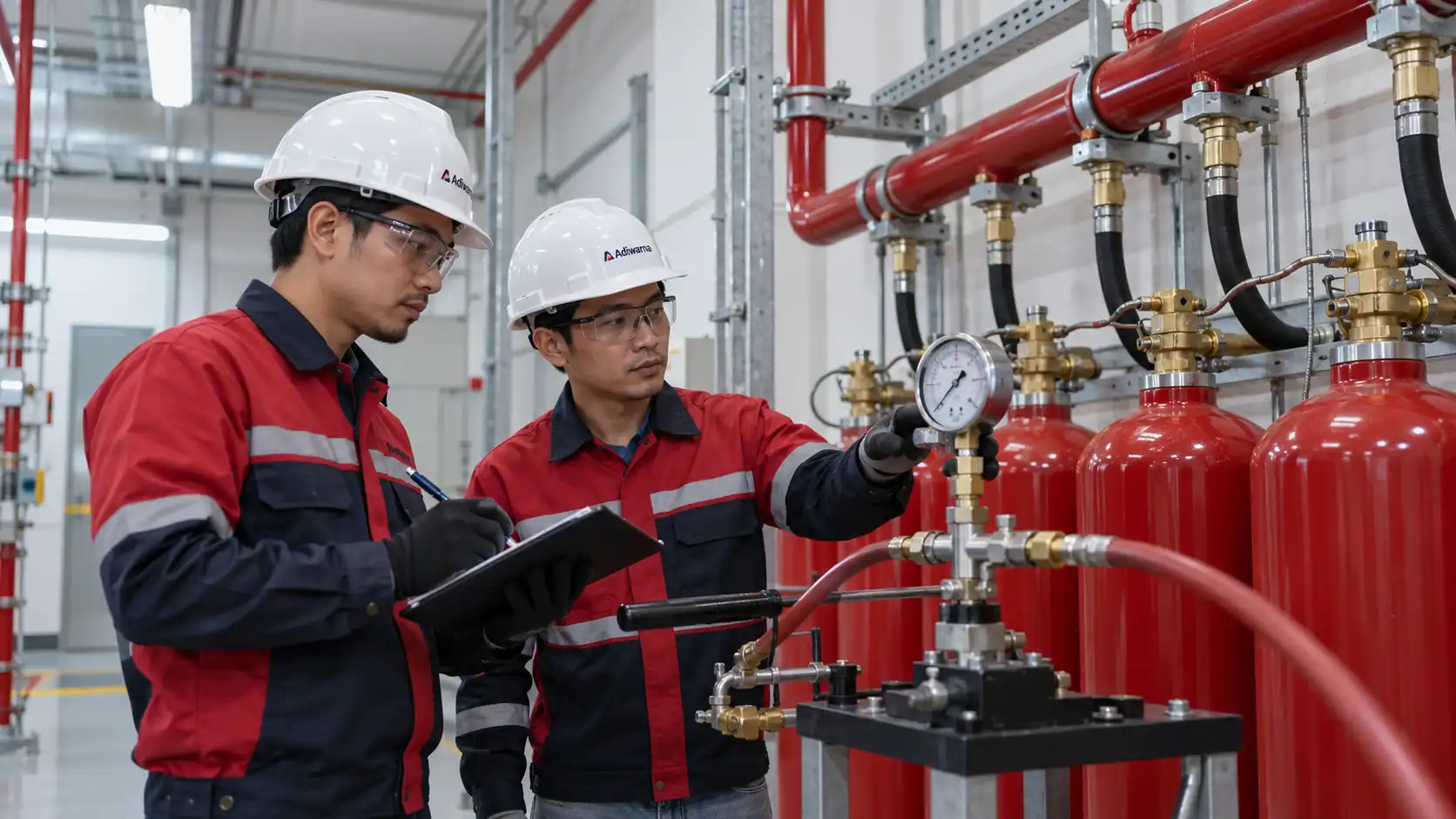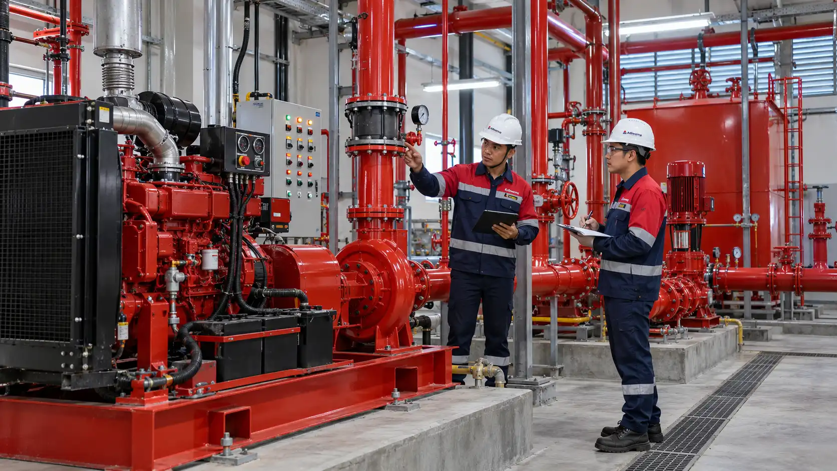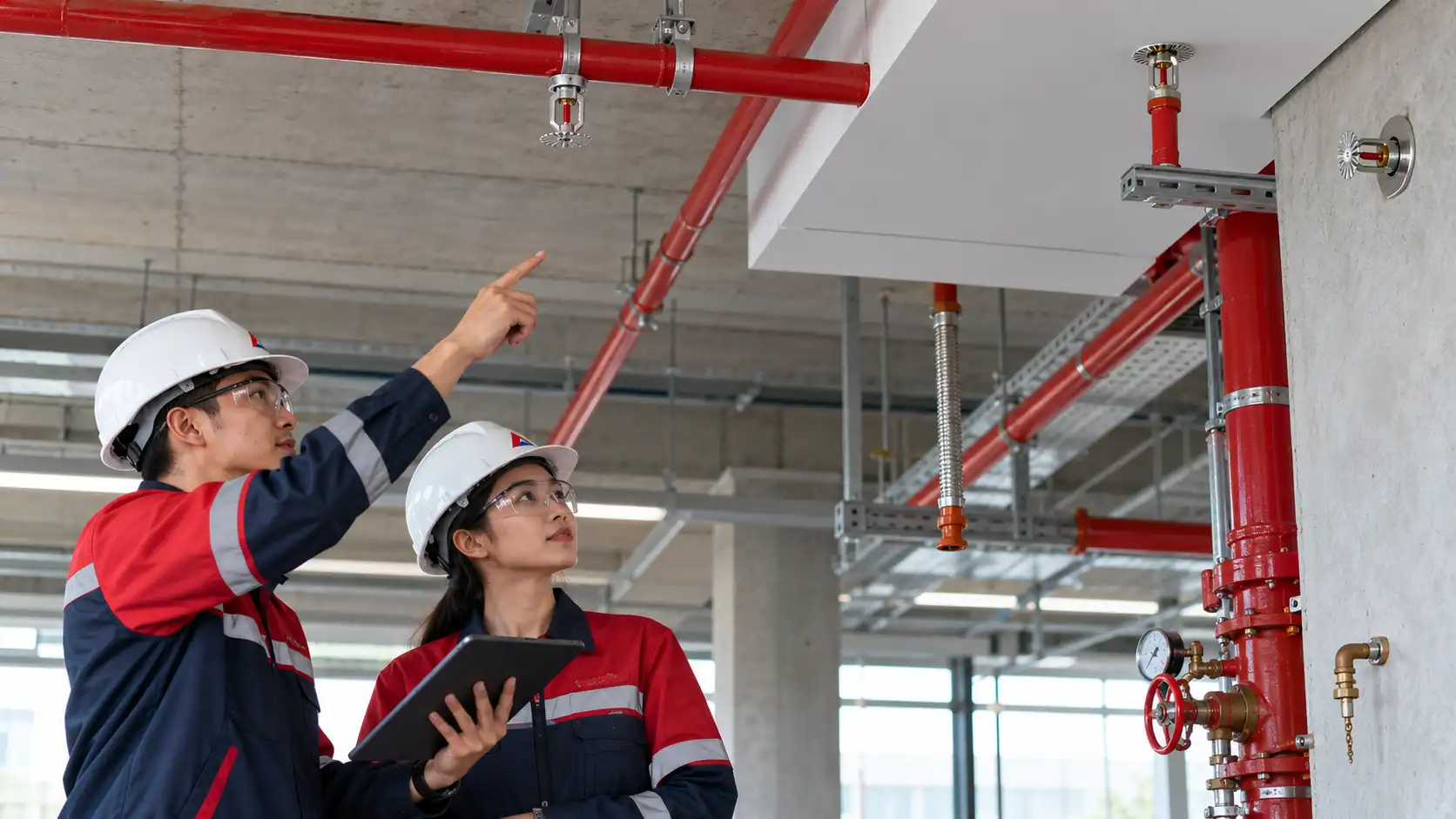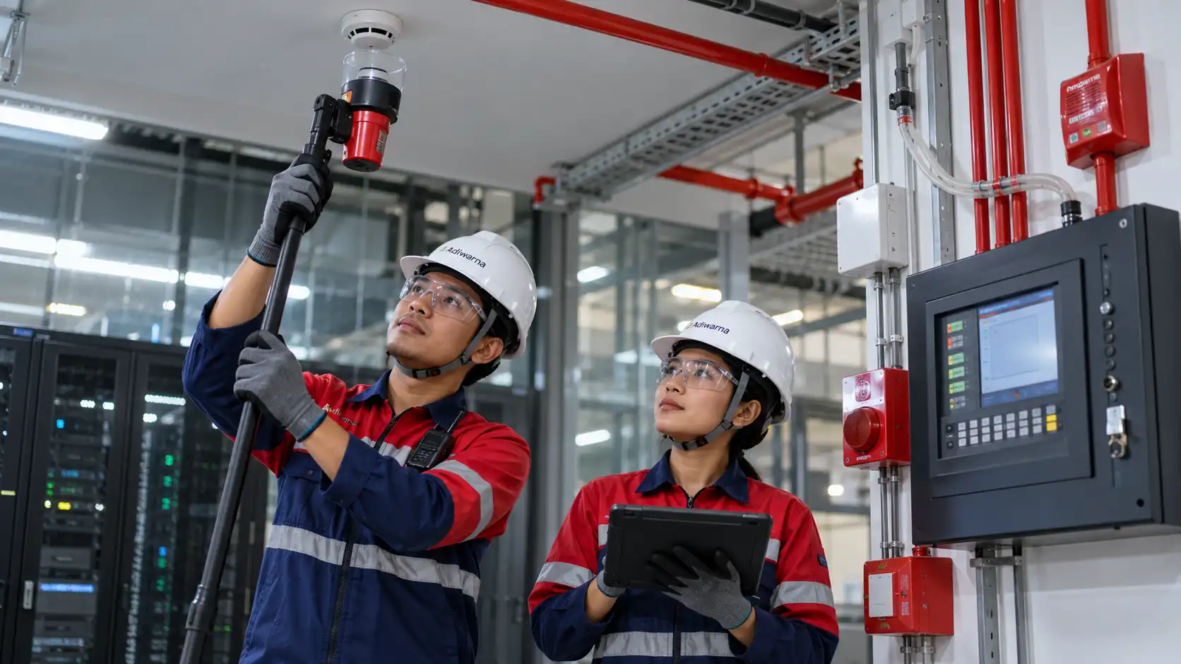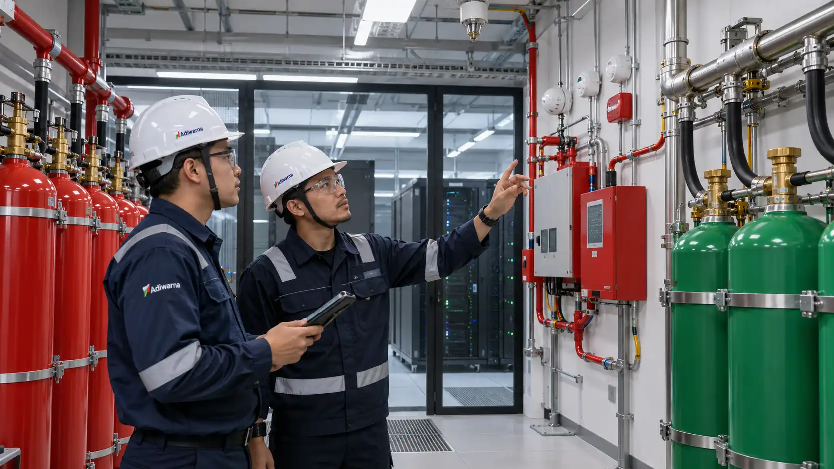

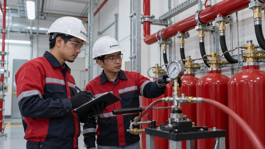
Gas Pipe is the focus of a structured review when the team needs to confirm pressure testing and integrity checks for clean-agent piping. The discussion is not limited to naming a component. Engineers must connect function, installation condition, interfaces, testing, and handover evidence so that the technical decision remains traceable.
In a real project, Gas Pipe should be read together with the approved drawings, method statement, manufacturer data, fire strategy, and AHJ requirements. This article takes a practical engineering approach: it explains what to inspect, why a finding matters, how to test the system, and when a retest or escalation is required.
Quick answer: what is Gas Pipe?
Gas Pipe in this article means a structured review of gas pipes, manifolds, cylinder valves, discharge nozzles, supports, threaded or grooved connections, and pressure-test equipment. The objective is to confirm that the components perform their intended function, are not affected by field changes, and can be supported by data. Values, settings, spacing, timing, capacity, and acceptance criteria should not be copied from another project without engineer review.
The final decision about Gas Pipe should consider occupancy, fire risk, room conditions, interaction with other systems, manufacturer instructions, and the standards adopted by the project. If documents conflict, do not close the finding by assumption; issue a clarification, record the decision basis, and obtain approval from the responsible party.
| Area | What is verified | Evidence |
|---|---|---|
| Design | approved piping drawings and isometrics | approved drawings, calculations, and design basis |
| Installation | material, diameter, fittings, supports, and bracing | photos, checklist, and as-built documents |
| Interface | test medium, isolation, gauge, and duration under the procedure | cause-and-effect, point list, and wiring |
| Testing | leakage, nozzle orientation, cylinder interface, and restoration | test record, deficiency, retest, and sign-off |
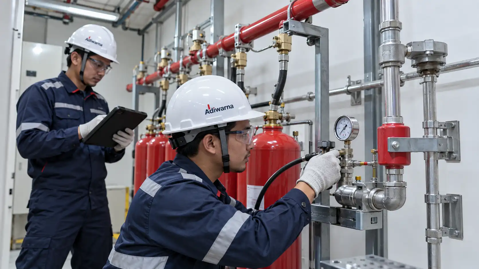
Gas Pipe design and installation
The first step is to compare the installed Gas Pipe with the approved drawings and data. Check location, orientation, access, material, supports, clearance, and relationships with adjacent components. Changes to ceilings, partitions, equipment layouts, cable trays, ducts, doors, or maintenance paths can change performance even when the main component appears unchanged.
The review must also cover interfaces. Gas Pipe may connect to detection, alarms, controllers, HVAC, lifts, BMS, shutdowns, water supplies, or other systems. Use one cause-and-effect matrix that agrees with programming and shop drawings. When feedback is required, define normal, alarm, supervisory, trouble, bypass, and restored conditions.
Field data to prepare for Gas Pipe
- approved piping drawings and isometrics
- material, diameter, fittings, supports, and bracing
- test medium, isolation, gauge, and duration under the procedure
- leakage, nozzle orientation, cylinder interface, and restoration
- device number, serial number, tag, and actual location
- initial condition, witness personnel, permit, and area controls
- configuration photos, drawing revision, and deficiency list
Gas Pipe testing and commissioning
Testing Gas Pipe should begin with a document review and an initial-condition check. Confirm that the area is safe, affected parties have been notified, impairments are controlled, instruments have a suitable range, and the tested system can be restored. Do not activate outputs that may disrupt building operations without a communication and restoration plan.
During the test, activate the defined input or condition under the approved procedure, then record time, location, panel status, outputs, feedback, and equipment condition. If Gas Pipe crosses disciplines, involve fire alarm, mechanical, electrical, BMS, operator, and owner representatives identified in the test plan. A comment that the system ‘works’ is not sufficient audit evidence.
Gas Pipe test sequence
- Review the approved drawings, calculations, cause-and-effect, method statement, and acceptance criteria.
- Perform a pre-test walkdown and record valve, power, panel, enclosure, access, or equipment conditions.
- Activate the test condition in a controlled way and document each component and interface response.
- Compare the result with the approved criteria and mark pass, deficiency, retest, or escalation.
- Restore the system, remove bypasses, complete the final walkdown, and retain the test record.
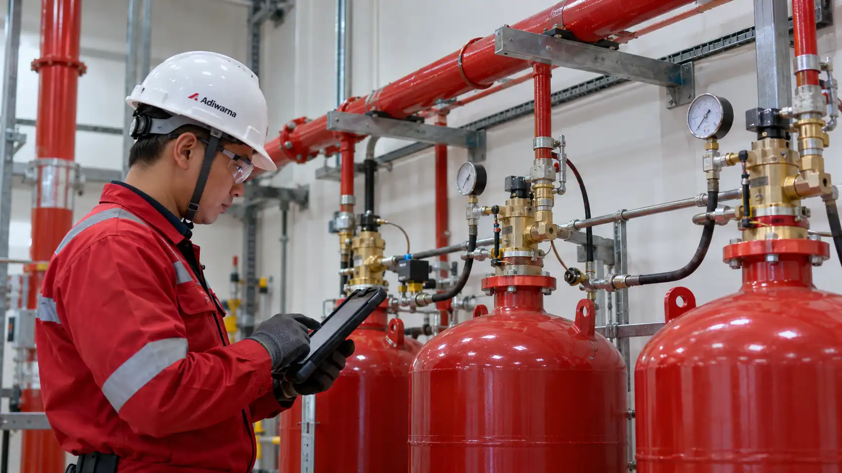
Standards and coordination for Gas Pipe
Use the following authoritative references when building the design and testing basis: the relevant NFPA reference and the related technical or standards reference. These links help identify available editions, but project application must follow the edition adopted by the contract, local regulation, AHJ, and manufacturer listing.
For projects in Indonesia, check the status of relevant SNI documents through the applicable BSN catalogue. Do not state that an SNI is mandatory, current, or a replacement for NFPA merely from an article title. Distinguish design, installation, acceptance, and inspection, testing, and maintenance functions. That document coordination makes the Gas Pipe decision defensible.
Common Gas Pipe mistakes
- Inspecting the Gas Pipe component visually without comparing it with the approved design.
- Using settings, spacing, or acceptance criteria from another project.
- Testing one device without testing the interfaces and feedback included in the sequence.
- Failing to record initial conditions, instruments, time, witnesses, and restoration status.
- Assuming that a stable result automatically means accurate or acceptable.
- Closing a deficiency without clear corrective action, evidence, and retesting.
Gas Pipe handover checklist
- The latest design documents, shop drawings, calculations, and revisions are available.
- Equipment, tags, serial numbers, locations, and maintenance access match the documents.
- Settings, valves, supports, clearances, interfaces, and labels have been checked.
- The test record includes raw data, test conditions, acceptance criteria, and sign-off.
- Deficiencies, corrective actions, retests, and close-out status are documented.
- As-built documents, O&M manuals, spare parts, training, and ITM schedules are handed over.
- The system has been restored to normal without forgotten bypasses or impairments.
FAQ: Gas Pipe
Is one Gas Pipe inspection enough?
No. Frequency and scope depend on the design, adopted standards, manufacturer instructions, environmental conditions, room changes, and the ITM program. Retesting is needed after changes or when results do not meet the criteria.
Who approves the Gas Pipe result?
Approval roles follow the project quality plan, witness matrix, contract, and AHJ authority. A technician may collect data, while acceptance should be reviewed by the appointed responsible parties.
Can photographs replace a Gas Pipe test record?
No. Photographs support configuration and field-condition evidence, but they do not replace numerical data, input-output status, method, time, criteria, and signatures.
When is consultation needed for Gas Pipe?
Consultation is appropriate when documents conflict, the room changes, a component is unlisted, readings are unstable, or cross-discipline interfaces do not have clear acceptance criteria.
Data quality and close-out
Decision quality also depends on how data is collected and preserved. Use a report format that identifies the document number, revision, date, location, personnel, instruments, initial conditions, actual results, acceptance criteria, and follow-up status. Preserve raw data with processed results so a reviewer can trace the calculation without relying on a screenshot or an operator’s memory.
Before closing the dossier, cross-check the test form, photographs, drawings, punch list, and change records. Every deficiency should have an owner, an action, evidence of completion, and a retest date when required. After close-out, store the report where operations and maintenance teams can access it; the record will support periodic inspection, troubleshooting, and improvement planning.
Conclusion: Gas Pipe
Reliable Gas Pipe performance comes from clear design, compliant installation, controlled testing, and traceable documentation. This approach helps owners distinguish a system that is genuinely ready from one that only appears active during a short inspection.
For Gas Pipe review, testing, or commissioning, review the related system or service, use fire-protection testing and commissioning support, and contact Adiwarna to discuss scope, documents, and survey needs.