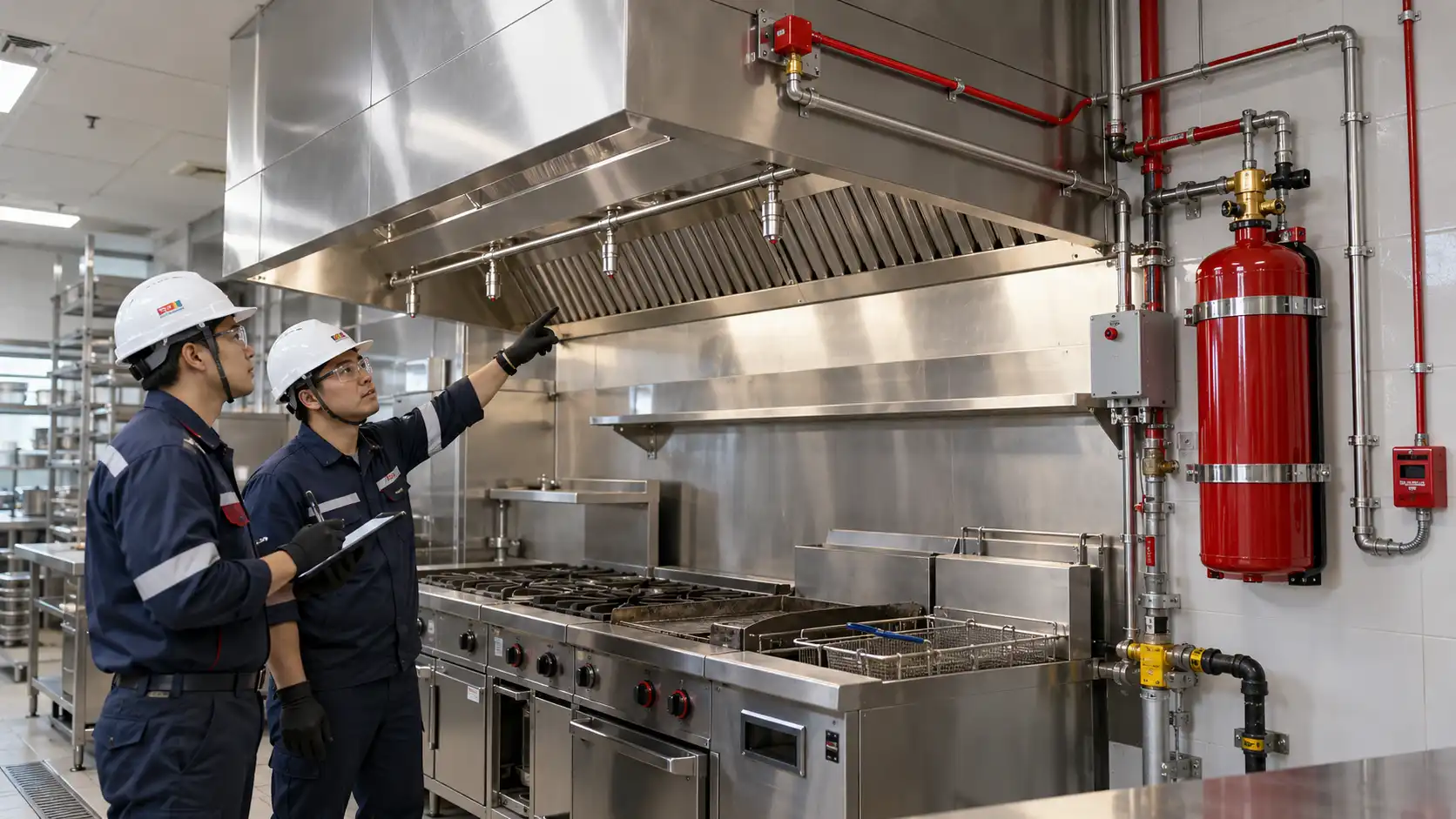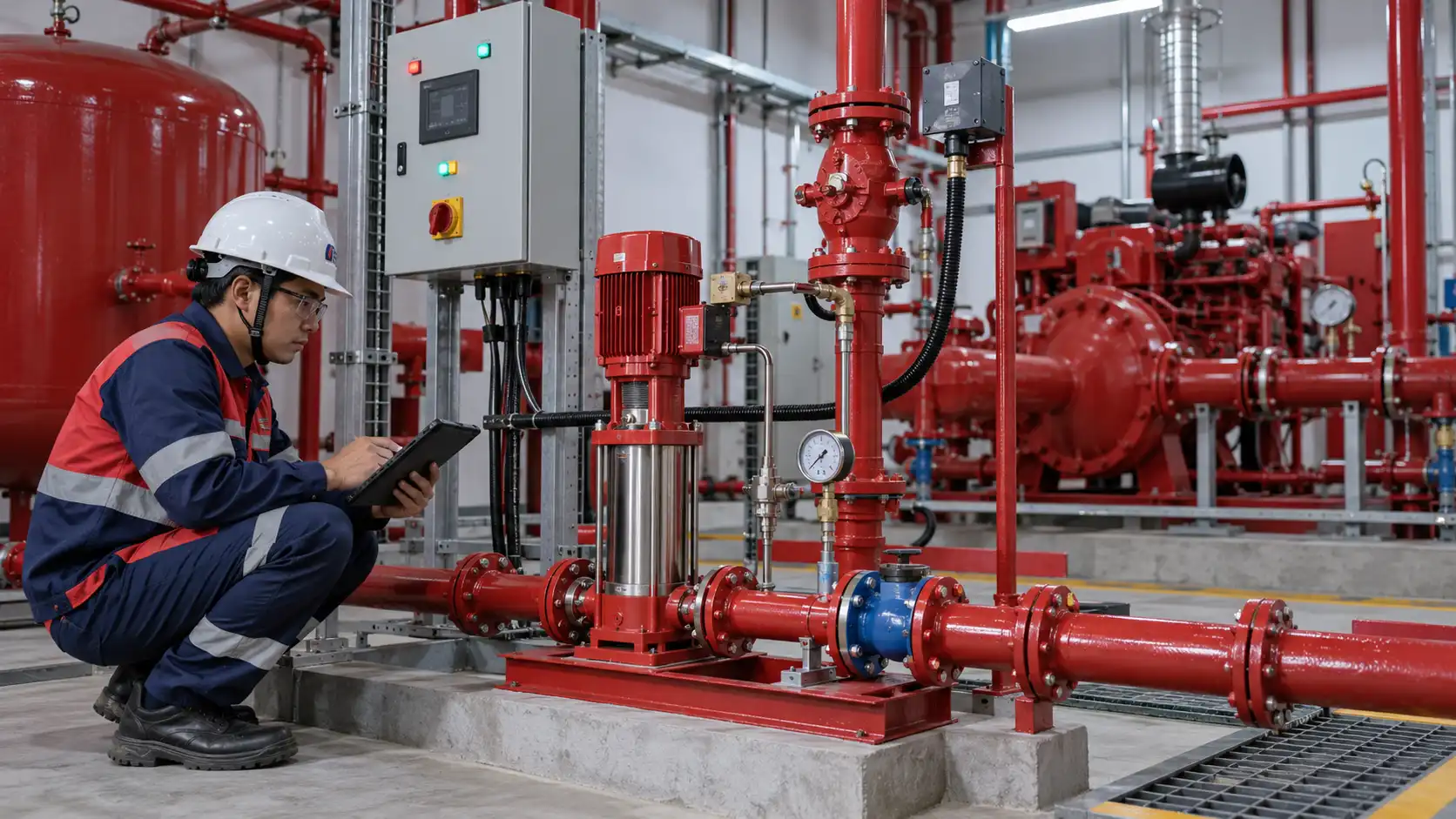


Cause and effect fire alarm is a structured method used to define the relationship between an event or input within a fire alarm system and the response or output that should occur after that event is received.
In a simple building, a smoke detector may only need to activate an alarm notification appliance. In a data center, hospital, high-rise building, industrial plant, or other critical facility, however, one fire alarm event can initiate several coordinated actions.
A typical sequence may look like this:
Detector activation → Fire Alarm Control Panel → Sounder/Strobe → BMS Signal → HVAC Shutdown → Damper Operation → Elevator Recall → Fire Suppression Logic
For this reason, a modern fire alarm system does much more than simply detect smoke and activate an alarm. It can also become an important coordination point for multiple emergency control functions.
The 2025 edition of NFPA 72 — National Fire Alarm and Signaling Code includes requirements covering documentation, inspection and testing, initiating devices, and emergency control function interfaces.
For projects involving several interconnected fire protection and life-safety systems, NFPA 4 provides an integrated testing framework intended to verify system operation and sequence of operation. NFPA LiNK currently lists a 2027 edition of NFPA 4.
Quick Answer
Cause and effect fire alarm is a matrix or sequence document showing what should happen when a specific fire alarm input becomes active.
For example:
Cause: Smoke Detector Alarm
Effect: Fire alarm indication, notification appliances, AHU shutdown, BMS indication, elevator recall, or suppression sequence.
The matrix supports:
- engineering;
- programming;
- interface coordination;
- functional testing;
- integrated commissioning;
- troubleshooting;
- handover documentation.
Adiwarna’s existing Testing Commissioning Fire Protection guide already places cause-and-effect testing within a broader integrated commissioning workflow involving fire alarm, HVAC, BMS, fire pumps, and suppression systems.
Read Adiwarna’s Testing Commissioning Fire Protection guide
What Is Cause and Effect Fire Alarm?
The terminology behind a cause and effect fire alarm system is relatively straightforward.
What Is a Cause?
A cause is an event, condition, or input detected or received by the fire alarm system.
Typical causes include:
- smoke detector alarm;
- heat detector alarm;
- flame detector alarm;
- manual call point activation;
- sprinkler waterflow switch;
- valve tamper switch;
- pressure switch;
- suppression-system pressure switch;
- fire pump status;
- gas detector;
- supervisory device.
What Is an Effect?
An effect is the response that should occur after the fire alarm system receives the cause.
Examples include:
- fire alarm indication;
- sounder activation;
- strobe activation;
- annunciator indication;
- BMS signal;
- AHU shutdown;
- fire damper command;
- smoke-control operation;
- elevator recall;
- access-control door release;
- pre-discharge warning;
- fire suppression release sequence;
- machinery shutdown.
Adiwarna’s English MCFA Fire Alarm article explains that modern main fire alarm control panels may interface with detectors, notification devices, suppression panels, lift controls, exhaust fans, and building management systems.
Learn about MCFA Fire Alarm systems
Why Is Cause and Effect Fire Alarm Important?
Without a clear cause and effect fire alarm matrix, the consultant, system programmer, installer, commissioning engineer, owner, and other contractors may interpret the required sequence differently.
Consider this example:
A smoke detector on Level 10 enters alarm.
Several questions immediately arise:
- Should every alarm in the building activate?
- Should only Level 10 activate?
- Should adjacent floors also receive notification?
- Should the AHU serving that floor stop?
- Should smoke or fire dampers move?
- Should elevators return to a recall level?
- Should BMS display the alarm?
- Should smoke control start?
- Should a suppression system enter a pre-discharge sequence?
These decisions should not be invented by a technician during final commissioning.
They should already be established through the:
fire strategy → approved design → sequence of operation → cause-and-effect matrix.
A properly developed matrix therefore connects:
Design Intent → Programming → Installation → Testing → Commissioning → Operation
Cause and Effect Fire Alarm vs Sequence of Operation
A cause-and-effect matrix and a sequence of operation usually describe the same intended behavior, but their presentation is different.
| Cause and Effect Matrix | Sequence of Operation |
|---|---|
| Usually presented as a table | Usually written as narrative text |
| Makes multiple input/output combinations easy to review | Explains system logic in detail |
| Useful for panel programming | Useful for design explanation |
| Highly practical during commissioning | Useful during design review |
| Can become a test checklist | Provides context behind the matrix |
Example Sequence of Operation
A narrative may state:
When the smoke detector in Zone A activates, the fire alarm system shall indicate the alarm condition, operate the required notification appliances, transmit the specified signal to the BMS, and initiate the approved HVAC response.
The same requirement can then be converted into rows and columns within the cause and effect fire alarm matrix.
How to Structure a Cause and Effect Fire Alarm Matrix
There is no single universal table format suitable for every building.
However, a common approach is:
Rows = Causes / Inputs
Columns = Effects / Outputs
For example:
| Cause | Panel Alarm | Sounder | BMS | AHU | Elevator | Suppression |
|---|---|---|---|---|---|---|
| Smoke Detector Zone 1 | ✓ | ✓ | ✓ | Stop | — | — |
| MCP Zone 1 | ✓ | ✓ | ✓ | Stop | Recall | — |
| Sprinkler Waterflow | ✓ | ✓ | ✓ | — | — | — |
| Cross-Zone Detection | ✓ | ✓ | ✓ | Stop | — | Pre-Release |
| Suppression Released | ✓ | ✓ | ✓ | Stop | — | Discharged |
A large data center, hospital, airport, industrial facility, or high-rise development may require hundreds of input-output combinations.
Cause Inputs in a Cause and Effect Fire Alarm Matrix
Smoke Detector
A smoke detector may initiate:
- local alarm;
- general alarm;
- BMS indication;
- fan shutdown;
- smoke-control sequence;
- suppression pre-alarm.
The required response depends on the approved fire strategy.
Heat Detector
Heat detectors may be used where environmental conditions make conventional smoke detection less appropriate.
The related effect must still be explicitly defined.
Flame Detector
Industrial facilities may use flame detection for hazards that can develop rapidly.
The detector may interface with:
- alarm systems;
- process shutdown;
- deluge;
- suppression;
- emergency control systems.
Manual Call Point
A manual call point allows an occupant or operator to manually initiate an alarm condition.
Its effect does not necessarily have to be identical to every automatic detector.
Sprinkler Waterflow Switch
Waterflow from an operating sprinkler system can generate an alarm signal through the fire alarm system.
Valve Supervisory Switch
A sprinkler or hydrant valve that moves away from its normal position typically generates a supervisory condition, rather than a normal fire alarm condition.
That distinction matters because operators should respond differently to:
Alarm ≠ Supervisory ≠ Trouble
Outputs in Cause and Effect Fire Alarm
A cause and effect fire alarm system can control or communicate with many systems beyond alarm bells.
Possible effects include:
- sounders and strobes;
- annunciators;
- fire command center;
- BMS;
- HVAC;
- smoke-control fans;
- fire dampers;
- smoke dampers;
- elevators;
- access control;
- clean agent suppression;
- fire pump indication;
- emergency power systems;
- machinery shutdown.
A key engineering principle is that verifying a relay output does not always prove that the final controlled equipment actually responded.
This distinction becomes important during integrated testing.
Cause and Effect Fire Alarm for HVAC
HVAC is one of the most common interfaces in a cause and effect fire alarm matrix.
A simplified sequence may be:
Smoke Detector
↓
Fire Alarm Panel
↓
Output Module
↓
AHU Stop Command
However, a commissioning engineer should not stop after confirming that the output module changed state.
The final question is:
Did the AHU actually stop?
If not, the failure could exist in:
- interface wiring;
- BMS logic;
- motor control;
- VFD logic;
- field relay;
- AHU controller.
Adiwarna’s fire protection commissioning article specifically emphasizes that testing should confirm the actual connected HVAC response, not only the fire alarm relay state.
This usually requires coordination between:
- fire alarm contractor;
- HVAC contractor;
- BMS contractor;
- commissioning engineer.
Cause and Effect Fire Alarm for Fire and Smoke Dampers
Fire and smoke dampers may also form part of the sequence.
For example:
Detector Alarm
↓
FACP Logic
↓
Control Module
↓
Damper Command
The actual logic may depend on:
- fire compartment;
- smoke-control strategy;
- HVAC zone;
- evacuation strategy;
- building design.
Therefore, a matrix should specify:
- which damper responds;
- which input triggers it;
- required position;
- feedback status;
- reset condition.
A blanket programming approach such as “all detectors close all dampers” is not automatically appropriate.
Cause and Effect Fire Alarm for Elevators
Elevators may interface with fire alarm systems for functions such as:
- primary recall;
- alternate recall;
- shaft detection response;
- elevator lobby detection response;
- other approved emergency functions.
The exact sequence should follow:
- elevator code;
- project fire strategy;
- approved design;
- AHJ requirements;
- elevator system requirements.
The fire alarm contractor should therefore coordinate with the elevator contractor instead of modifying elevator logic independently.
Cause and Effect Fire Alarm for BMS
A BMS may receive multiple signals from the fire alarm system.
Examples include:
- General Fire Alarm;
- Zone Alarm;
- Fire Pump Running;
- Valve Supervisory;
- Fire Alarm Trouble;
- Suppression Released;
- Clean Agent System Trouble.
Integrated testing should verify:
- correct point mapping;
- correct device description;
- correct location;
- correct signal type;
- alarm priority;
- reset behavior;
- status updates.
A BMS indication should not automatically be treated as a substitute for dedicated fire alarm functions required by the approved system.
Cause and Effect Fire Alarm for Fire Pumps
A fire pump controller can provide status signals to the fire alarm or BMS.
Example:
| Cause | Effect |
|---|---|
| Electric Fire Pump Running | Running indication |
| Diesel Fire Pump Running | Running indication |
| Controller Trouble | Trouble indication |
| Pump Room Condition | Response according to design |
The matrix should follow the approved controller interfaces.
Fire alarm logic should not arbitrarily replace or interfere with fire pump controller safety functions.
Cause and Effect Fire Alarm for Sprinkler Systems
Sprinkler systems commonly interface with the fire alarm system through:
- waterflow switches;
- valve supervisory switches;
- pressure switches.
Waterflow Sequence
Sprinkler Waterflow
↓
Fire Alarm Panel
↓
Alarm Notification
↓
Control Room / BMS Indication
Valve Supervisory Sequence
Valve Leaves Normal Position
↓
Supervisory Signal
This distinction helps operators understand whether they are dealing with an active fire condition or an impairment in the protection system.
Cause and Effect Fire Alarm for Fire Suppression Systems

Clean agent and inert gas suppression systems can require one of the most complex fire alarm sequences.
Adiwarna’s English Fire Suppression System for Buildings and Industry page lists cross-zone logic testing, releasing-panel tests, HVAC shutdown testing, BMS interface testing, cause-and-effect testing, room integrity testing, and final system restoration as potential commissioning activities.
Read Adiwarna’s Fire Suppression System guide
First Detector Condition
A first detector may generate:
- alarm indication;
- pre-alarm;
- operator notification.
Cross-Zone Confirmed
When the required second detection condition occurs, possible effects may include:
- pre-discharge alarm;
- sounder/strobe;
- HVAC shutdown;
- damper action;
- release time delay;
- release circuit enablement.
Agent Release
Following release, the system may generate:
- discharge indication;
- pressure-switch status;
- BMS indication;
- system status update.
The final logic must follow the approved suppression design, manufacturer documentation, applicable clean-agent standard, and project requirements.
Cause and Effect Fire Alarm for Data Centers
Data centers are among the best examples of why a detailed cause and effect fire alarm matrix is necessary.
A facility may contain:
- aspirating smoke detection;
- addressable fire alarm;
- preaction sprinkler;
- clean agent suppression;
- BMS;
- DCIM;
- CRAH/CRAC units;
- dampers;
- UPS room protection;
- access control.
A possible hierarchy can be:
Early Warning
Aspirating Detection
↓
Pre-Alarm
Confirmed Fire
Confirmed Detection
↓
Fire Alarm
Suppression Condition
Cross-Zone Detection
↓
Pre-Discharge Logic
↓
HVAC Isolation
↓
Release Sequence
Because a data center prioritizes operational continuity, poorly designed sequences can cause unnecessary downtime even when the detection system itself functions correctly.
Adiwarna’s English fire suppression content and room-integrity guidance both emphasize integrated testing and enclosure performance for critical facilities.
Read Adiwarna’s Room Integrity Test guide
Cause and Effect Fire Alarm for Hospitals
Hospitals require special fire strategy considerations because some occupants may not be capable of immediate self-evacuation.
A matrix may involve:
- alarm zoning;
- nurse station indication;
- smoke compartments;
- HVAC response;
- fire/smoke dampers;
- elevator interfaces;
- smoke control;
- public-address systems.
Therefore, an office-building matrix should not simply be copied into a hospital project.
The response sequence should match the actual healthcare fire strategy.
Cause and Effect Fire Alarm for Industrial Facilities
Industrial facilities may contain more complex interfaces involving:
- gas detection;
- ESD;
- process shutdown;
- deluge systems;
- foam systems;
- ventilation shutdown;
- machinery;
- suppression systems;
- DCS;
- PLC.
The fire alarm system is not automatically the master controller for every industrial shutdown.
A good system architecture should clearly define the boundary between:
Fire Alarm → ESD → PLC → DCS → Process Equipment
Adiwarna’s English deluge-system article also includes detector testing, solenoid activation, automatic fire pump operation, flow verification, and cause-and-effect testing within commissioning activities.
Explore Adiwarna’s Deluge System Fire Protection guide
Cause and Effect Fire Alarm in Addressable Systems
An addressable fire alarm system provides detailed control because each device has a unique address.
Logic can therefore be developed based on:
- device;
- floor;
- zone;
- room;
- hazard;
- group;
- time;
- cross-zone condition.
For example:
Detector L10-023
can generate a different response from:
Detector L10-024
even though both are installed on Level 10.
This flexibility makes naming conventions, address lists, and documentation particularly important.
Cause and Effect Fire Alarm in Conventional Systems
A conventional fire alarm system can also support cause-and-effect logic.
However, control is generally based on zones rather than individual detector addresses.
For example:
Zone 3 Alarm
may produce:
- local notification;
- relay activation;
- AHU shutdown;
- BMS signal.
The matrix should therefore reflect the actual capabilities of the installed fire alarm architecture.
NFPA 72 and Cause and Effect Fire Alarm
NFPA 72:2025 — National Fire Alarm and Signaling Code is a key technical reference for fire alarm and signaling systems.
The 2025 edition includes chapters covering:
- documentation;
- inspection, testing, and maintenance;
- initiating devices;
- emergency control function interfaces;
- protected premises alarm and signaling systems.
Access NFPA 72:2025 through NFPA LiNK
However, an important distinction should be maintained:
NFPA 72 does not mean that every project must use one identical universal cause-and-effect table layout.
The matrix is an engineering and commissioning tool used to convert the approved design intent into testable input-output logic.
Its format may be established by:
- consultant requirements;
- owner requirements;
- project specifications;
- AHJ;
- system integrator;
- commissioning requirements.
NFPA 4 and Cause and Effect Fire Alarm Testing
When fire alarm inputs trigger responses in other systems, integrated testing becomes critical.
NFPA 4 — Standard for Integrated Fire Protection and Life Safety System Testing is intended to verify operation and the sequence of operation of interconnected systems. NFPA technical documentation describes verification of system function, sequence, manufacturer requirements, and record documentation as part of integrated testing.
NFPA LiNK currently lists a 2027 edition of NFPA 4, alongside the 2024 and earlier editions.
A useful distinction is:
NFPA 72 → fire alarm and signaling system/interface requirements
NFPA 4 → integrated end-to-end system testing
Actual project compliance should follow the edition adopted or specified for that project.
NFPA 3 and Cause and Effect Fire Alarm
NFPA 3 addresses the commissioning process for fire protection and life-safety systems.
Cause-and-effect logic is relevant throughout commissioning because it affects:
- design review;
- interface coordination;
- functional testing;
- integrated testing;
- deficiency tracking;
- documentation;
- handover.
NFPA LiNK currently lists 2027 and 2024 editions of NFPA 3, along with earlier editions.
For an actual project, the design team should use the edition required by the contract, AHJ, applicable regulation, or project specification.
Cause and Effect Fire Alarm in Testing and Commissioning
A cause and effect fire alarm matrix should be tested systematically rather than through random device activation.
Step 1 — Review the Approved Matrix
Confirm that the latest revision is available.
Step 2 — Select the Cause
For example:
Smoke Detector SD-01 — Server Room A
Step 3 — Activate the Input
Use the appropriate test method for the device.
Step 4 — Verify the Fire Alarm Panel
Check:
- device address;
- location text;
- signal type;
- alarm condition.
Step 5 — Verify Notification
Confirm the required:
- sounder;
- strobe;
- annunciator.
Step 6 — Verify External Interfaces
Check:
- HVAC;
- BMS;
- dampers;
- elevators;
- suppression;
- other controlled equipment.
Step 7 — Verify Reset
Confirm proper system restoration.
Step 8 — Record the Result
Record:
- expected response;
- actual response;
- deficiency;
- corrective action;
- retest result.
Adiwarna’s English commissioning article explains that integrated commissioning should verify the complete interaction of fire alarm, BMS, HVAC, fire pump, and suppression systems rather than checking components only in isolation.
Cause and Effect Fire Alarm End-to-End Testing

One of the most important commissioning principles is:
Do not stop at the relay.
Assume the matrix requires:
Smoke Detector → AHU Shutdown
An incomplete test would be:
Detector activated → Output relay changed state → PASS.
A stronger end-to-end test would be:
Detector activated → Fire alarm panel received the input → Output module operated → Interface transmitted the command → AHU actually stopped → Final condition verified.
This difference matters because a relay may operate even when:
- field wiring is broken;
- the BMS mapping is incorrect;
- the VFD logic rejects the command;
- the AHU controller fails;
- the damper actuator does not move.
NFPA 4’s integrated-testing approach focuses on verifying interconnected system performance and sequence, rather than only isolated component operation.
Cause and Effect Fire Alarm Checklist
Before final commissioning, review:
- Latest approved cause-and-effect matrix available
- Matrix revision matches current drawings
- Device addresses match actual locations
- Zone mapping verified
- Alarm conditions verified
- Supervisory conditions verified
- Trouble conditions verified
- Sounder and strobe logic verified
- BMS points verified
- AHU shutdown tested
- Damper operation tested
- Elevator interface tested
- Fire pump indications verified
- Sprinkler waterflow verified
- Valve supervisory signals verified
- Suppression sequence tested
- Manual release tested where applicable
- Abort logic tested where applicable
- System reset verified
- Deficiencies documented
- Corrective actions completed
- Affected sequences retested
- Final matrix included in handover documentation
Common Cause and Effect Fire Alarm Mistakes
Using an Outdated Matrix
The installation changes, but the matrix still refers to an earlier revision.
Inconsistent Device Naming
The fire alarm panel, BMS, drawings, and matrix use different equipment names.
Treating Relay Activation as the Final Effect
The interface activates, but nobody confirms the actual controlled equipment response.
Excluding Other System Contractors
HVAC, BMS, elevator, and suppression contractors may need to participate in integrated testing.
Copying Another Project’s Matrix
Every facility has its own:
- fire strategy;
- zoning;
- occupancy;
- smoke-control concept;
- evacuation strategy.
Mixing Alarm, Supervisory, and Trouble
Different signal types require different responses.
Skipping Retesting
When logic is corrected, the affected sequence should be tested again.
Troubleshooting Cause and Effect Fire Alarm
When the expected effect does not occur, troubleshooting should follow the signal path systematically.
Step 1 — Was the Cause Detected?
Check the initiating device.
Step 2 — Did the Fire Alarm Panel Receive It?
Verify:
- address;
- zone;
- signal type.
Step 3 — Did the Panel Execute the Logic?
Review panel programming.
Step 4 — Did the Output Module Operate?
Check the fire alarm output.
Step 5 — Did the Interface Receive the Command?
Inspect wiring and interface logic.
Step 6 — Did the Controlled System Respond?
Verify the final:
- AHU;
- damper;
- elevator;
- BMS;
- suppression system.
This method is more reliable than immediately modifying the panel program without first identifying where the sequence failed.
Cause and Effect Fire Alarm Documentation
The handover package should contain more than a panel programming printout.
Useful documents include:
- final cause-and-effect matrix;
- sequence of operation;
- as-built fire alarm drawings;
- device list;
- address list;
- input/output list;
- interface diagrams;
- panel configuration backup;
- commissioning reports;
- deficiency records;
- retest records;
- operation manuals.
NFPA 72:2025 contains a dedicated documentation chapter, reinforcing the importance of maintaining system records throughout the lifecycle.
When Should a Cause and Effect Fire Alarm Matrix Be Updated?
The matrix should be reassessed following modifications such as:
- new detectors;
- changed zones;
- tenant renovation;
- AHU replacement;
- BMS upgrade;
- elevator modification;
- fire pump controller changes;
- suppression replacement;
- new dampers;
- changes in room function;
- building expansion.
For this reason, the cause-and-effect matrix should be treated as a living engineering document.
It should not remain unchanged for years while the actual facility continues to evolve.
Cause and Effect Fire Alarm for Existing Buildings
Existing facilities may have problems such as:
- missing matrix;
- undocumented programming;
- obsolete as-built drawings;
- replacement fire alarm panels;
- upgraded BMS;
- modified HVAC;
- changed system integrators.
A practical recovery process may be:
Site Survey → Device Mapping → Programming Review → Functional Testing → Rebuild Matrix → Integrated Testing
The resulting documentation can become the new baseline for:
- operation;
- maintenance;
- troubleshooting;
- future retrofit.
Who Should Develop the Cause and Effect Fire Alarm Matrix?
Ideally, the matrix should come from the approved fire strategy and design intent.
It should not be created solely by the person programming the fire alarm panel.
Relevant participants may include:
- fire protection consultant;
- fire alarm designer;
- MEP engineer;
- system integrator;
- HVAC engineer;
- BMS engineer;
- elevator contractor;
- suppression engineer;
- commissioning team;
- owner representative.
The fire alarm programmer then converts the approved logic into the system configuration.
Who Should Approve the Cause and Effect Fire Alarm Matrix?
The approval path depends on project organization.
It may involve:
- consultant;
- engineer of record;
- owner;
- commissioning authority;
- main contractor;
- specialist contractor;
- AHJ.
Critical sequence changes should therefore use a controlled approval process rather than informal site instruction.
How to Choose a Cause and Effect Fire Alarm Contractor
A contractor handling cause and effect fire alarm work should understand more than control-panel programming.
Evaluate whether the provider can:
- Review fire alarm drawings.
- Interpret the sequence of operation.
- Develop input-output matrices.
- Differentiate alarm, supervisory, and trouble signals.
- Coordinate HVAC interfaces.
- Coordinate BMS integration.
- Coordinate elevator interfaces.
- Integrate fire suppression.
- Perform functional testing.
- Perform end-to-end testing.
- Troubleshoot interface failures.
- Prepare final documentation.
- Support complete testing and commissioning.
Adiwarna presents its business as an integrated fire protection contractor, and its English site covers hydrant, sprinkler, fire alarm, fire suppression, and related engineering solutions.
Explore Adiwarna Fire Protection Solutions
Cause and Effect Fire Alarm by Adiwarna
PT Adiwarna Anugerah Abadi Tbk can support an integrated workflow covering:
Design Review
↓
Cause-and-Effect Development
↓
Panel Programming
↓
Interface Coordination
↓
Functional Testing
↓
Integrated Testing
↓
Documentation & Handover
This approach is valuable because a cause-and-effect failure often occurs between different systems, rather than inside the fire alarm panel itself.
For example:
- fire alarm works but HVAC does not respond;
- suppression panel works but BMS mapping is wrong;
- detector works but elevator interface fails.
The objective is therefore to verify the complete integrated response.
FAQ About Cause and Effect Fire Alarm
What Is Cause and Effect Fire Alarm?
Cause and effect fire alarm is a structured document defining the relationship between fire alarm inputs and the outputs or responses they should produce.
A smoke detector may be a cause, while alarm notification, BMS indication, AHU shutdown, or elevator recall may be effects.
What Is a Cause and Effect Matrix?
A cause-and-effect matrix is a table mapping individual system inputs against required outputs.
It supports:
- design;
- programming;
- testing;
- commissioning;
- troubleshooting.
Does NFPA 72 Cover Cause and Effect Fire Alarm?
NFPA 72 covers fire alarm and signaling systems, including documentation, initiating devices, testing, and emergency control function interfaces.
However, it is not accurate to claim that every project must use one universal matrix format.
What Is the Difference Between NFPA 72 and NFPA 4?
NFPA 72 primarily addresses fire alarm and signaling systems and their interfaces.
NFPA 4 addresses integrated testing of interconnected fire protection and life-safety systems to verify intended operation and sequence.
What Are Examples of Fire Alarm Causes?
Examples include:
- smoke detector;
- heat detector;
- manual call point;
- sprinkler waterflow;
- suppression pressure switch.
What Are Examples of Fire Alarm Effects?
Examples include:
- sounder/strobe activation;
- BMS indication;
- AHU shutdown;
- damper movement;
- elevator recall;
- fire suppression sequence.
What Is Cross-Zone Detection?
Cross-zone detection is logic in which more than one detection condition is required before a particular response is initiated.
It is commonly associated with gaseous fire suppression release sequences.
Can a BMS Replace a Fire Alarm Panel?
Not automatically.
The responsibilities of the fire alarm system and BMS should follow the approved design and applicable project requirements.
Should Cause and Effect Be Tested?
Yes.
A matrix existing only on paper does not demonstrate that the installed systems actually perform the intended sequence.
When Should the Matrix Be Updated?
It should be reviewed after changes involving:
- detector layout;
- zones;
- HVAC;
- BMS;
- elevators;
- dampers;
- suppression;
- panel programming;
- system interfaces.
Consult Adiwarna for Cause and Effect Fire Alarm
Cause and effect fire alarm connects the approved engineering design with actual building-system response.
A detector may operate perfectly, yet the overall emergency sequence can still fail if programming or interfaces are incorrect.
PT Adiwarna Anugerah Abadi Tbk can support:
- fire alarm engineering;
- design review;
- device mapping;
- cause-and-effect development;
- system programming;
- BMS coordination;
- HVAC interfaces;
- suppression integration;
- functional testing;
- integrated testing;
- commissioning;
- documentation.
For project evaluation, prepare:
- latest fire alarm drawings;
- device list;
- existing matrix;
- sequence of operation;
- HVAC information;
- BMS information;
- suppression information;
- project specifications.
Contact Adiwarna for fire alarm and system integration consultation
Conclusion
Cause and effect fire alarm is one of the most important engineering tools in an integrated modern fire alarm system.
The matrix connects:
Cause / Input → Fire Alarm Logic → Interface → Effect / Output
A complex facility can involve a sequence such as:
Detector → Fire Alarm → Notification → BMS → HVAC → Damper → Elevator → Suppression
NFPA 72 provides the primary technical framework for fire alarm and signaling systems, while NFPA 4 supports integrated verification of interconnected fire protection and life-safety systems. NFPA 3 supports the broader commissioning process.
A well-designed, programmed, tested, and documented cause and effect fire alarm therefore gives the owner much more than proof that a detector activates.
It provides evidence that the complete fire protection response follows the intended sequence when a fire scenario occurs.